/*
VernierThermistorDisplay (v 2017.07)
Reads the temperature from a Vernier Stainless Steel Temperature Probe (TMP-BTA)
or Surface Temperature Sensor (STS-BTA) connected to the BTA connector.
As written, the readings will be displayed every half second. Change the variable
TimeBetweenReadings to change the rate.
This version of the program uses the VernierLib library.
See www.vernier.com/engineering/stem/sensors/temperature-sensor/
for more information on how thermistors are read.
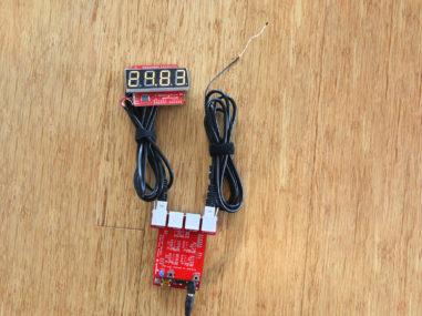
This sketch uses a 4-character, 7-Segment Serial Display to temperature
readings in Celsius. The code for controlling the display was based on
the Serial 7-Segment Display Example Code, Serial Mode Stopwatch by Jim Lindblom
of SparkFun Electronics
The print function is used with the SoftwareSerial library
to send display data to the S7S.
Here is the wiring for display with a UART serial connection:
Arduino -------------- Serial 7-Segment
5V -------------------- VCC
GND -------------------- GND
13 -------------------- RX
*/
#include "VernierLib.h"
VernierLib Vernier;
float sensorReading;
#include <SoftwareSerial.h>
// These are the Arduino pins required to create a software serial
// instance. We'll actually only use the TX pin.
const int softwareTx = 9;
const int softwareRx = 7;
SoftwareSerial s7s(softwareRx, softwareTx);
char tempString[10]; // Will be used with sprintf to create strings
int thermistorPIN =0;// Analog Pin 0
float readingTime;
int count; //reading from the A/D converter (10-bit)
float temp;
unsigned int temp100;
int timeBetweenReadings = 500; // in ms
int readingNumber=0;
void setup()
{
Vernier.autoID();// this is the routine to do the autoID
s7s.begin(9600);
// Clear the display, and then turn on all segments and decimals
clearDisplay(); // Clears display, resets cursor
setDecimals(0b000000); // Turn on all decimals, colon, apos
s7s.print("DEG."); // Displays Deg and then Cels on display
delay (2000);
s7s.print("CELS");
setBrightness(127); // Medium brightness
delay(1500);
setBrightness(255); // High brightness
delay(1500);
// Clear the display before jumping into loop
clearDisplay();
}
void loop()
{
sensorReading =Vernier.readSensor();
Serial.print(sensorReading);
temp100 =sensorReading*100;
// Magical sprintf creates a string for us to send to the s7s.
// The %4d option creates a 4-digit integer.
sprintf(tempString, "%4d", temp100);
// This will output the tempString to the S7S
s7s.print(tempString);
setDecimals(0b0000010); // Sets digit 3 decimal on
delay(timeBetweenReadings); // This will make the display update at about every half second
}
void clearDisplay()
{
s7s.write(0x76); // Clear display command
}
// Set the displays brightness. Should receive byte with the value
// to set the brightness to
// dimmest------------->brightest
// 0--------127--------255
void setBrightness(byte value)
{
s7s.write(0x7A); // Set brightness command byte
s7s.write(value); // brightness data byte
}
// Turn on any, none, or all of the decimals.
// The six lowest bits in the decimals parameter sets a decimal
// (or colon, or apostrophe) on or off. A 1 indicates on, 0 off.
// [MSB] (X)(X)(Apos)(Colon)(Digit 4)(Digit 3)(Digit2)(Digit1)
void setDecimals(byte decimals)
{
s7s.write(0x77);
s7s.write(decimals);
}