Go Direct® Force and Acceleration Sensor User Manual
Order Code: GDX-FOR
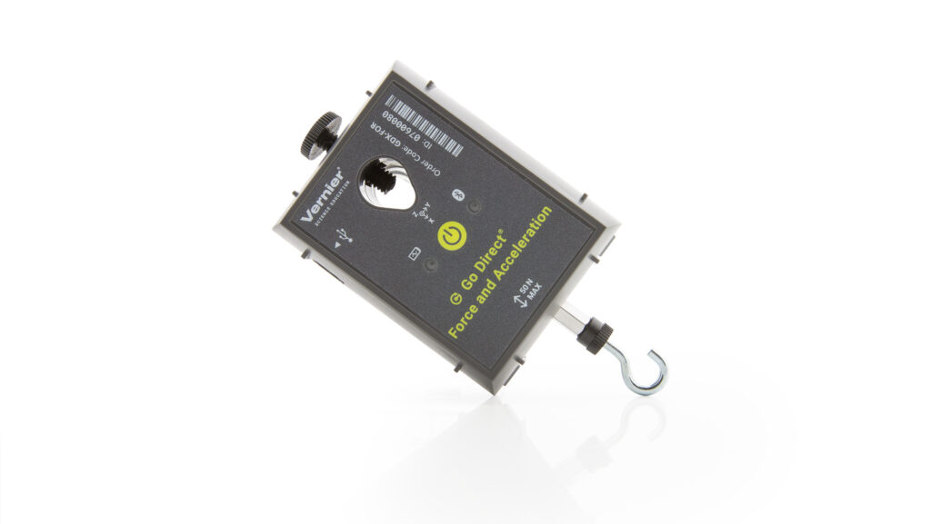
Go Direct Force and Acceleration couples a 3-axis accelerometer with a stable and accurate force sensor that measures forces as small as ±0.1 N and up to ±50 N.
Note: Vernier products are designed for educational use. Our products are not designed nor are they recommended for any industrial, medical, or commercial process such as life support, patient diagnosis, control of a manufacturing process, or industrial testing of any kind.
What's Included
- Go Direct Force and Acceleration
- Hook
- Bumper
- Nylon screw
- Accessory rod
- Micro USB Cable
Compatible Software
Choose a platform below to see its compatibility requirements.LabQuest
Interface LabQuest App LabQuest 3 Full support LabQuest 2 (discontinued) Full support 1 LabQuest (discontinued) Incompatible Compatibility Notes
Computers
Software Interface Graphical Analysis No interface required Full support 1 LabQuest 3 Full support 2 LabQuest 2 (discontinued) Full support 2 3 Compatibility Notes
Chromebook
Software Interface Graphical Analysis No interface required Full support LabQuest 3 Full support 1 LabQuest 2 (discontinued) Full support 1 2 Compatibility Notes
iOS
Software Interface Graphical Analysis Graphical Analysis GW No interface required Full support Full support LabQuest 3 Full support 1 2 Full support 1 2 LabQuest 2 (discontinued) Full support 1 2 3 Full support 1 2 3 Compatibility Notes
Android
Software Interface Graphical Analysis Graphical Analysis GW No interface required Full support Incompatible LabQuest 3 Full support 1 2 Full support 1 LabQuest 2 (discontinued) Full support 1 2 3 Full support 1 3 Compatibility Notes
Python
Software Interface Python No interface required Full support Javascript
Software Interface Javascript No interface required Full support 1 Compatibility Notes
LabVIEW
Software Interface NI LabVIEW No interface required Full support 1 Compatibility Notes
Assembly
The hook and bumper attach to the sensor by screwing them into the post.
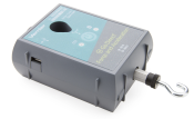
Hook attached
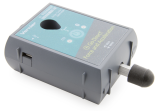
Bumper attached
Getting Started
Please see the following link for platform-specific connection information:
|
Bluetooth Connection |
USB Connection |
|
Note: This sensor does not work with the original LabQuest. It works with LabQuest 2 or LabQuest 3. |
Charging the Sensor
Connect Go Direct Force and Acceleration to the included Micro USB Cable and any USB device for two hours.
You can also charge up to eight Go Direct Force and Acceleration Sensors using our Go Direct Charge Station, sold separately (order code: GDX-CRG). An LED on each Go Direct Force and Acceleration indicates charging status.
| Charging |
Orange LED next to battery icon is solid while sensor is charging. |
| Fully charged |
Green LED next to battery icon solid when sensor is fully charged. |
Powering the Sensor
| Turning on the sensor |
Press button once. Red LED indicator next to Bluetooth icon flashes when unit is on. |
| Putting the sensor in sleep mode |
Press and hold button for more than three seconds to put into sleep mode. Red LED indicator stops flashing when sleeping. |
Connecting the Sensor
See the following link for up-to-date connection information:
Connecting via Bluetooth
| Ready to connect | Red LED next to Bluetooth icon flashes when sensor is awake and ready to connect. |
| Connected | Green LED next to Bluetooth icon flashes when sensor is connected via Bluetooth. |
Connecting via USB
| Connected and charging | Orange LED next to battery icon is solid when sensor is connected to Graphical Analysis via USB and the unit is charging. LED next to Bluetooth icon is off. |
| Connected, fully charged | Green LED next to battery icon is solid when sensor is connect to Graphical Analysis via USB and fully charged. LED next to Bluetooth icon is off. |
| Charging via USB, connected via Bluetooth |
Orange LED next to battery icon is solid when sensor is connected to charger via USB and the unit is charging. Green LED next to Bluetooth icon flashes when sensor is connected via Bluetooth. |
Identifying the Sensor
When two or more sensors are connected, the sensors can be identified by tapping or clicking Identify in Sensor Information.
Using the Product
Connect the sensor following the steps in the Getting Started section of this user manual.
Channels
Go Direct Force and Acceleration has seven measurement channels. The channel names are
- Force
- X-axis acceleration
- Y-axis acceleration
- Z-axis acceleration
- X-axis gyro
- Y-axis gyro
- Z-axis gyro
Force
The default channel that is active when the sensor is connected is Force. The force channel measures pushes and pulls along the main axis of the sensor body. Use the hook attachment for pulling and the bumper attachment for pushing. Pulls are registered as positive forces and pushes are registered as negative forces, unless sensor readings are reversed in Graphical Analysis.
Acceleration
There are three acceleration channels, measured by a single chip, which is located under the 3-axis icon on the label. The icon shows the positive direction for each axis, with the x-direction of acceleration parallel to the pulling force on the force sensor and the z-direction straight up through the label. Each direction of acceleration can be measured separately.
If you choose to activate all three acceleration channels at once, you can create a calculated column for the total acceleration magnitude.
Gyroscope
Use the gyroscope channels to measure the rotation rate of the unit. Measured values are positive when the rotation is counter-clockwise relative to the axis directions indicated by the 3-axis icon on the label. For example, when placed label upward on a turntable rotating clockwise, the x- and y- gyroscopes will read close to zero and the z- gyroscope will show a negative reading.
If you choose to activate all three gyroscope channels at once, you can create a calculated column for the total magnitude of angular velocity.
Collecting Data with Go Direct Centripetal Force Apparatus
Slide Go Direct Force and Acceleration onto the Go Direct Centripetal Force Apparatus beam. Attach the mass carriage to the apparatus and secure the sensor at the desired location. As you turn the spindle to rotate the apparatus beam, the sensor will apply the force necessary to pull the carriage in a circular motion.
Channels
Turn on the sensor and connect it to Graphical Analysis on your device. Select the appropriate Go Direct Force and Acceleration data-collection channels in Graphical Analysis for your investigation:
- Z-axis gyro to capture angular velocity
- X-axis acceleration for centripetal acceleration
- Force for centripetal force
For additional information, refer to www.vernier.com/til/4258
Calibrating the Sensor
Force
This sensor is factory calibrated. If you would like to calibrate the force sensor yourself, use a two-point calibration: no force applied and a known force applied. It is easiest to simply hang a mass from the hook. We recommend a 1 kg mass or greater. Do not exceed the maximum of 50 N during calibration.
Acceleration
This sensor is factory calibrated.
Gyroscope
This sensor is factory calibrated.
Specifications
|
Response time |
1 ms |
|
Force range |
±50 N |
|
Acceleration range |
±156.8 m/s2 |
|
Gyroscope range |
±34.9 rad/s |
|
Maximum sampling rate |
1,000 samples/s |
|
USB specification |
USB 2.0 full speed |
|
Wireless specification |
Bluetooth v4.2 |
|
Maximum wireless range |
30 m (unobstructed) |
|
Dimensions |
|
|
Battery |
300 mAh Li-Poly Rechargeable |
|
Battery life (single full charge) |
~10 hours continuous data collection |
|
Battery life (long term) |
~300 full charge cycles (several years depending on usage) |
Care and Maintenance
Battery Information
Go Direct Force and Acceleration contains a small lithium-ion battery. The system is designed to consume very little power and not put heavy demands on the battery. Although the battery is warranted for one year, the expected battery life should be several years. Replacement batteries are available from Vernier (order code: GDX-BAT-300).
Storage and Maintenance
To store Go Direct Force and Acceleration for extended periods of time, put the device in sleep mode by holding the button down for at least three seconds. The red LED will stop flashing to show that the unit is in sleep mode. Over several months, the battery will discharge but will not be damaged. After such storage, charge the device for a few hours, and the unit will be ready to go.
Exposing the battery to temperatures over 35°C (95°F) will reduce its lifespan. If possible, store the device in an area that is not exposed to temperature extremes.
Water Resistance
Go Direct Force and Acceleration is not water resistant and should never be immersed in water.
If water gets into the device, immediately power the unit down (press and hold the power button for more than three seconds). Disconnect the sensor and charging cable, and remove the battery. Allow the device to dry thoroughly before attempting to use the device again. Do not attempt to dry using an external heat source.
How the Sensor Works
Force
The force channel uses strain gauge technology to measure force based on the bending of a beam in a load cell.
Accelerometer
The accelerometer is a microelectromechanical device (MEMS device) consisting of a cantilever and a test mass. As the mass is accelerated, the cantilever bends, generating a signal proportional to the acceleration. Three orthogonal axes provide three channels of acceleration information.
Gyroscope
The gyroscope is a microelectromechanical device that uses a vibrating structure to determine rate of rotation using the Coriolis force on the structure. Three orthogonal axes provide three different channels of rotation information.
Additional Information about Acceleration
Since the Accelerometer is sensitive to both acceleration and the Earth’s gravitational field, interpreting accelerometer measurements is complex. A useful model for understanding accelerometer measurements is a spring-based scale with a reference mass (or object) attached to the scale. If the scale is pointing upward (the usual orientation for such a device) the weight of the mass causes the spring to compress, and you get a non-zero reading. If you were to turn the scale upside down, the spring will be extended, instead of compressed, and we get a reading of the opposite sign. If you turn the scale so it points sideways, and keep it motionless, then the spring will just be at its relaxed length, and the reading will be zero. If you accelerated the scale toward the mass, then the spring would compress. If you accelerate the scale away from the mass the spring would stretch. In each case the scale is reading a value corresponding to the normal force on the mass. This reading can be made relative by dividing out the mass, giving units of N/kg, which is the same as m/s2.
Q: What does an accelerometer measure?
A: Normal force per unit mass, otherwise known as proper acceleration.
Note that it’s not the net force per unit mass (which is acceleration), but it is the normal force per unit mass. This somewhat unusual quantity corresponds with what a rider on a roller coaster feels during the turns. This interpretation is useful even for the scalar total acceleration value, which is 9.8 N/kg for a 3-axis accelerometer at rest, zero for one in free fall, and greater than 9.8 for one rounding a corner.
This normal force interpretation works even for a one-axis accelerometer being accelerated in a horizontal direction. The reading is non-zero as the test mass inside the device has to have a force applied to accelerate it. That’s just a normal force that happens to be horizontal.
When discussing the accelerometer reading, we can call it the Normal Force per Unit Mass, with units of N/kg.
Q: I thought the Accelerometer measured acceleration!
A: Here we are being very careful to not call something an acceleration when it is not a kinematic acceleration. For example, an “acceleration” of 9.8 m/s2 for an object that remains at rest is clearly a problematic interpretation, yet that’s what the accelerometer reads.
You can correct the Accelerometer reading to get a true acceleration by adding the component of the gravitational acceleration field along the direction of the sensor arrow. For example, if the axis of the accelerometer is pointing upward, then the gravitational component is –9.8 m/s2. The Accelerometer reads 9.8 m/s2 when the arrow is upward and the device is at rest. By adding –9.8 m/s2, we get zero, which is the correct acceleration. If the arrow is horizontal, then the reading is zero, but the gravitational component is zero, and we still have zero for the true acceleration.
Q: What about g-force measurements?
A: We avoid the term g-force because the quantity doesn’t have units of force. Instead, g-factor can be used as a simplified label for Normal Force per Unit Mass in axis labels and discussions.
You can see that the g-factor is then 1 for an object sitting at rest on a table, zero in free fall, etc. The g-factor is dimensionless. If the Normal Force is a vector, then so is the g-factor. g-factor is completely optional–it is just a shortcut to avoid a long name.
Repair Information
If you have followed the troubleshooting steps and are still having trouble with your Go Direct Force and Acceleration, contact Vernier Technical Support at support@vernier.com or call 888-837-6437. Support specialists will work with you to determine if the unit needs to be sent in for repair. At that time, a Return Merchandise Authorization (RMA) number will be issued and instructions will be communicated on how to return the unit for repair.
Accessories/Replacements
| Item | Order Code |
|---|---|
| Dual Range Force Sensor Replacement Parts Kit |
DFS-RPK |
| Bumper and Launcher Kit |
BLK |
| Accessory Rod |
ACC-ROD |
| Adapter for Pasco Cart |
PCA-DFS |
| Force Table Adapter |
FTA-DFS |
| Go Direct Centripetal Force Apparatus | GDX-CFA |
|
GDX-BAT-300 |
|
|
CB-USB-MICRO |
|
|
CB-USB-C-MICRO |
Warranty
Warranty information for this product can be found on the Support tab at www.vernier.com/gdx-for/#support
General warranty information can be found at www.vernier.com/warranty
Disposal
When disposing of this electronic product, do not treat it as household waste. Its disposal is subject to regulations that vary by country and region. This item should be given to an applicable collection point for the recycling of electrical and electronic equipment. By ensuring that this product is disposed of correctly, you help prevent potential negative consequences on human health or on the environment. The recycling of materials will help to conserve natural resources. For more detailed information about recycling this product, contact your local city office or your disposal service.
Battery recycling information is available at www.call2recycle.org
Do not puncture or expose the battery to excessive heat or flame.
 The symbol, shown here, indicates that this product must not be disposed of in a standard waste container.
Contact Support
Fill out our online support form or call us toll-free at 1-888-837-6437.