Go Direct® Photogate User Manual
Order Code: GDX-VPG
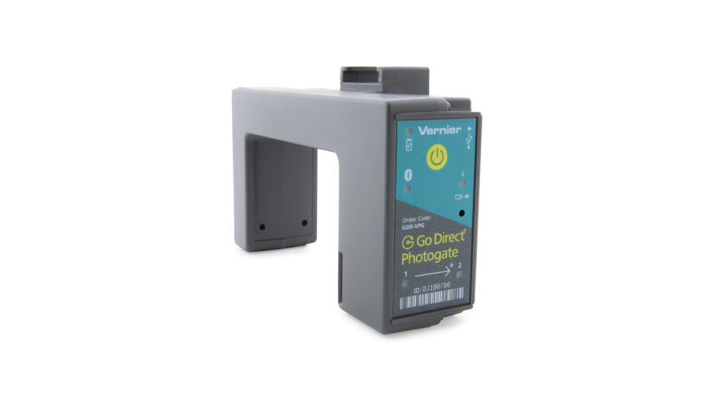
Go Direct Photogate is used for velocity, acceleration, and timing measurements of objects passing through the gate. The object blocks infrared beams as it passes through the gate. Motion data can be determined from the timing of beam blocking.
This general-purpose photogate can be used for a wide variety of experiments in physics and physical science classes. Examples include
- measuring the speed of a rolling object
- measuring freefall acceleration
- measuring the acceleration of a cart on a ramp
- studying the swing of a pendulum
- timing the period of a rotating object
- measuring the speed of objects undergoing collisions
Go Direct Photogate is a double-gate sensor that includes two photogates built into the arms of the sensor. This configuration allows for accurate velocity measurements without needing to know anything about the geometry of the object. The internal gates can also be used individually as traditional single-gate photogates when desired. Go Direct Photogate also includes a single laser gate for use with objects passing outside of the arms of the sensor. Using the laser gate requires a visible-light pen laser (not included).
Go Direct Photogate can be used alone or with other Go Direct Photogates. An optional accessory cable (order code: VPG-CB-GDX) allows you to daisy-chain two Go Direct Photogates together to increase the timing accuracy for measurements between two gates.
Note: Vernier products are designed for educational use. Our products are not designed nor are they recommended for any industrial, medical, or commercial process such as life support, patient diagnosis, control of a manufacturing process, or industrial testing of any kind.
What's Included
- Go Direct Photogate
- Accessory Rod
- Micro USB Cable
Compatible Software
Choose a platform below to see its compatibility requirements.LabQuest
Interface LabQuest App LabQuest 3 Full support LabQuest 2 (discontinued) Full support 1 LabQuest (discontinued) Incompatible Compatibility Notes
Computers
Software Interface Graphical Analysis No interface required Full support 1 LabQuest 3 Full support 2 LabQuest 2 (discontinued) Full support 2 3 Compatibility Notes
Chromebook
Software Interface Graphical Analysis No interface required Full support LabQuest 3 Full support 1 LabQuest 2 (discontinued) Full support 1 2 Compatibility Notes
iOS
Software Interface Graphical Analysis Graphical Analysis GW No interface required Full support Incompatible LabQuest 3 Full support 1 2 Full support 1 LabQuest 2 (discontinued) Full support 1 2 3 Full support 1 3 Compatibility Notes
Android
Software Interface Graphical Analysis Graphical Analysis GW No interface required Full support Incompatible LabQuest 3 Full support 1 2 Full support 1 LabQuest 2 (discontinued) Full support 1 2 3 Full support 1 3 Compatibility Notes
Python
Software Interface Python No interface required Full support Javascript
Software Interface Javascript No interface required Full support 1 Compatibility Notes
LabVIEW
Software Interface NI LabVIEW No interface required Full support 1 Compatibility Notes
Getting Started
Please see the following link for platform-specific connection information:
|
Bluetooth Connection |
USB Connection |
|
Note: This sensor does not work with the original LabQuest. It works with LabQuest 2 or LabQuest 3. |
Charging the Sensor
Connect the included Micro USB Cable to the Go Direct Photogate and then to any USB device for two hours.
You can also charge up to eight Go Direct Photogates using our Go Direct Charge Station, sold separately (order code: GDX-CRG). An LED on each Go Direct Photogate indicates charging status.
| Charging |
LED indicator next to the battery icon is orange while sensor is charging. |
| Fully charged |
LED indicator next to the battery icon is green when sensor is fully charged. |
Powering the Sensor
| Turning on the sensor |
Press the power button once. LED indicator next to the Bluetooth icon flashes red when unit is on. |
| Putting the sensor in sleep mode |
Press and hold the power button for more than three seconds to put into sleep mode. LED indicators are off when sleeping. |
Connecting the Sensor
See the following link for up-to-date connection information:
Connecting via Bluetooth Wireless Technology
| Ready to connect | LED indicator next to the Bluetooth icon flashes red when sensor is awake and ready to connect to software. |
| Connected | LED indicator next to Bluetooth icon flashes green when sensor is connected to software via Bluetooth. |
Connecting via USB
| Connected and charging | LED indicator next to the battery icon is solid orange and the LED indicator next to the Bluetooth indicator is off when sensor is connected to software via USB and the unit is charging. |
| Connected, fully charged | LED indicator next to the battery icon is solid green and the LED indicator next to the Bluetooth icon is off when sensor is connect to software via USB and is fully charged. |
| Charging via USB, connected via Bluetooth |
LED indicator next to the battery icon is solid orange and the LED indicator next to the Bluetooth icon flashes green when the sensor is connected to software via Bluetooth and the unit is charging. |
Identifying the Sensor
Use the Identify feature to flash the LED indicator next to the Bluetooth icon on the sensor to which you are connected. In Graphical Analysis, Identify is accessed from Sensor Information. In LabQuest App, Identify is accessed by tapping the sensor meter, then tapping Go Direct.
Using the Product
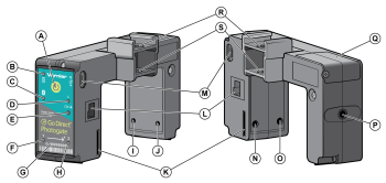
- Power button
- Charging LED indicator
- Bluetooth LED indicator
- Laser gate LED indicator
- Laser gate photodiode
- Gate 1 LED indicator
- Sensor ID number
- Gate 2 LED indicator
- Gate 1 photodiode
- Gate 2 photodiode
- Bar tape guide
- Daisy-chain accessory port
- Micro-USB port
- Gate 2 infrared emitter diode
- Gate 1 infrared emitter diode
- 1/4-20 mounting nut
- Battery door
- Pulley bracket attachment point
- Ultra pulley attachment points
Sensor Channels
Connect the sensor following the steps in the Getting Started section of this user manual. Go Direct Photogate has multiple sensor channels that provide a variety of data options for measuring the motion of an object. The sensor channels include
- Object Velocity
- Object Acceleration (multiple flags)
- Gate 1 – Gate State
- Gate 2 – Gate State
- Laser Gate – Gate State
- Remote Gate – Object Velocity
- Remote Gate – Object Acceleration
- Gate 1/Remote Gate – Timing
- Laser Gate/Remote Gate – Timing
Object-based Sensor Channels
The object-based sensor channels are unique to Go Direct Photogate. These sensor channels make use of the double-gate design for measurement of velocity and acceleration. The object-based channel measurements do not depend on the geometry of the object or its direction of motion through the gate.
Object Velocity
This channel is the default sensor channel of Go Direct Photogate. The channel reports the velocity of an object as it passes through the arms of Go Direct Photogate. This is similar to using a pair of traditional photogates in Pulse-Timing mode.
Velocities are calculated by finding the time interval associated with the successive blocking of the two internal gates. This time interval is referred to as the pulse time. The ratio of the distance between the internal gates (2.0 cm) and the pulse time is reported as the magnitude of the object’s velocity. An object that first blocks Gate 1 then blocks Gate 2 will report positive velocities. An object that first blocks Gate 2 then blocks Gate 1 will report negative velocities. Velocity measurements can be displayed with units of m/s (default), cm/s, or ft/s.
The default data-collection mode for Object Velocity is Time-based. While collecting data, velocities and their associated time values are recorded. The reported time value, referred to as the velocity mid-time, is determined by averaging the times used for the pulse-time calculation. You can make multiple velocity measurements in the same data set; however, it may be necessary to adjust the experiment duration in order to collect your desired data.
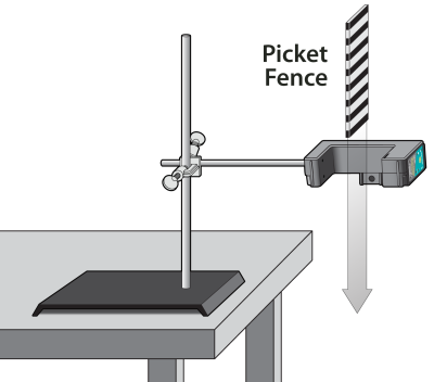
Objects with multiple flags, such as a picket fence, will report velocity measurements for each flag as the object passes through the gate. It is not necessary to have one flag completely pass through both gates before the subsequent flag enters the gate, such as happens when using a Vernier Cart Picket Fence. Corresponding blocked events for the two internal gates are used when reporting velocities for multi-flagged objects.
For objects that have multiple flags, the average of the multiple velocity measurements can be used to represent the average velocity of the object. The slope of the best-fit line through the Velocity vs. Time data can be used to calculate the average acceleration of the object as it passed through the gate.
Object Acceleration (multiple flags)
This sensor channel reports the acceleration of objects having two or more flags that break the internal photogate beams while passing through the gate. This is similar to using a pair of traditional photogates in Gate-and-Pulse-Timing mode.
Accelerations are calculated using velocity and velocity mid-time values calculated for each flag as described in the Object Velocity section. The ratio of the difference in successive flag velocity measurements and the difference in their associated velocity mid-time values is reported as the object’s acceleration. The acceleration values can be displayed with units of m/s2 (default), cm/s2, or ft/s2.
The default data-collection mode for Object Acceleration is Time-based. While collecting data, accelerations and their associated time values are recorded. The reported time value, referred to as the acceleration mid-time, is determined by averaging the velocity mid-time values used for the acceleration value calculation. You can make multiple acceleration measurements in the same data set; however, it may be necessary to adjust the experiment duration in order to collect your desired data.
Objects with more than two flags, such as a picket fence, will report acceleration measurements for each successive pair of flags as the object passes through the gate. It is not necessary to have one flag completely pass through both gates before the subsequent flag enters the gate, such as happens when using a Vernier Cart Picket Fence. Corresponding successive flag-velocity measurements for the two internal gates are used when calculating accelerations for multi-flagged objects.
For objects that have more than two flags, the average of the multiple acceleration measurements can be used to represent the average acceleration of the object.
Tips for using Object-Based Sensor Channels
- To ensure you get accurate velocity and acceleration measurements, your object should start outside the arms of the photogate and pass completely through the gate without reversing the direction of motion partway through the gate. When this is not followed, the reported data may not accurately reflect the object’s motion.
- We do not recommend using these sensor channels with pulleys, wheels, or bar tape as these objects cannot be made to start completely outside the gates.
- Velocity measurements are only displayed when the second gate is blocked within one second of the first gate being blocked.
- Acceleration measurements require an object to have two or more “flags” break the internal photogate beams while passing through the gate.
- Accelerations are only displayed when, for each flag, the second gate is blocked within one second of the first gate, and when the second flag blocks its first gate within one second of the first flag unblocking its second gate.
- Sensor meters for object-based sensor channels will update as objects pass through the Go Direct Photogate; however, measurements are not stored in the software unless you are actively collecting data.
- The default data-collection mode for object-based sensor channels is Time-based. No values are recorded for these sensor channels when using Photogate Timing modes.
Gate-State Sensor Channels
Gate-State sensor channels report the same data that our traditional photogates report. You can use these sensor channels along with object-based sensor data collection to explore and verify velocity and acceleration calculations. The gate-state channels can be used with Photogate Timing modes for additional data-collection options including replication of traditional photogate data-collection experiments. The channels can also be used on their own in time-based mode if you want to require students to do hand calculations using photogate data.
Gate 1 – Gate State
This sensor channel reports changes in gate state and associated times for Gate 1.
Gate 2 – Gate State
This sensor channel reports changes in gate state and associated times for Gate 2.
Laser Gate – Gate State
This sensor channel reports the gate state changes and the associated times for the Laser Gate. Selecting this channel activates the Laser Gate on the Go Direct Photogate. This channel cannot be used with other sensor channels except Laser Gate/Remote Gate – Timing.
To use the Laser Gate, a visible-light pen laser (not included) must be pointed at the Laser Gate photodiode (located below the ![]() icon) on the Go Direct Photogate. The Laser Gate LED indicator will be solid blue when the laser is not aligned or when the gate is blocked. The Laser Gate LED indicator will be off when the Laser Gate sensor channel is selected, the laser is aligned, and the gate is unblocked.
icon) on the Go Direct Photogate. The Laser Gate LED indicator will be solid blue when the laser is not aligned or when the gate is blocked. The Laser Gate LED indicator will be off when the Laser Gate sensor channel is selected, the laser is aligned, and the gate is unblocked.
Note: It may be easier to adjust the laser first for the desired path, and then place the gate so that it aligns with the laser beam (Laser Gate LED indicator turns off).
Tips for using Gate-State Sensor Channels
- When gate-state channels are the only channels selected, the default data-collection mode is set to Photogate Timing.
- Gate-state values for blocking events are reported as 1.
- Gate-state values for unblocking events are reported as 0.
- Use gate-state sensor channels for experiments involving linear or angular motion timing (position, velocity, and acceleration measurements), pendulum timing, and object timing (time between gates).
- The times associated with blocking events are used in the pulse-time calculations for Object Velocity and Object Acceleration channels.
- The Projectile Launcher Photogate Timing option cannot be used with Go Direct Photogates as the sensor channels are not configured the same as on a Projectile Launcher.
- When using a Vernier Ultra Pulley Attachment (not included), you must use the Gate 2 – Gate State sensor channel as the pulley does not block Gate 1.
Remote-Gate Sensor Channels
The Remote Gate sensor channels are used when a Go Direct Photogate is daisy-chained to a second Go Direct Photogate or to a Time of Flight Pad. Using these channels require accessory cables not included with the Go Direct Photogate.
When two Go Direct Photogates are daisy-chained together, you can connect either of the photogates to your device via USB or Bluetooth® wireless connection. Once the first gate is connected, the second gate becomes the “Remote Gate” of the connected photogate. The Remote Gate or the Time of Flight Pad are set up using the connected sensor’s Remote-Gate sensor channels.
Remote Gate – Object Velocity
This sensor channel reports Object Velocity values for the Remote Gate when two Go Direct Photogates are daisy-chained together. See Object Velocity for details on the reported data.
Remote Gate – Object Acceleration
This sensor channel reports Object Acceleration values for the Remote Gate when two Go Direct Photogates are daisy-chained together. See Object Acceleration (multiple flags) for details on the reported data.
Gate 1/Remote Gate – Timing
This sensor channel reports the time between successive blocked events for Gate 1 of the connected gate and Gate 1 of the daisy-chained Remote Gate or Time of Flight Pad. This pulse time does not depend on the order the gates are blocked and is reported at the time the second gate is blocked.
Laser Gate/Remote Gate – Timing
This sensor channel reports the time between successive blocked events between the Laser Gate of the connected gate and Gate 1 of the daisy-chained Remote Gate or Time of Flight Pad. This pulse time does not depend on the order the gates are blocked and is reported at the time the second gate is blocked.
Selecting this sensor channel activates the Laser Gate on the Go Direct Photogate. This channel cannot be used with other sensor channels except for Laser Gate – Gate State. See Laser Gate – Gate State for instructions on setting up a Laser Gate.
Tips for using Remote-Gate Sensor Channels
- The default data-collection mode for Remote-Gate sensor channels is Time-based. No values are recorded for these sensor channels when using Photogate Timing modes.
- Objects with multiple flags will report multiple timing values. The average of the multiple timing measurements can be used to represent the average time for the object to pass between the two gates.
- You cannot use the Laser Gate on a daisy-chained Remote Gate. To collect data using two Go Direct Photogates both in Laser Gate mode, connect both sensors directly to your device.
- You cannot get the gate-state data from a daisy-chained Remote Gate. To collect data using two Go Direct Photogates both in Gate-State modes, connect both sensors directly to your device.
Experiments Using Go Direct Photogate
Go Direct Photogates can be used for several experiments in the books Physics with Vernier, Advanced Physics with Vernier — Mechanics, and Physics Explorations and Projects. See these books for detailed experiments. Here are some brief examples of things you can do with a photogate.
Note: Additional equipment not included with the Go Direct Photogate may be required to do these experiments.
- Experiment: Measure the acceleration due to the gravity of an object in freefall using a Vernier Picket Fence.
Sensor channel: Object Velocity or Object Acceleration
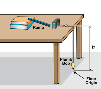
Mode: Time-based - Experiment: Determine the launch speed of a projectile launched horizontally.
Sensor channel: Object Velocity
Mode: Time-based - Experiment: Find the launch speed and time of flight of a projectile using a Go Direct Photogate and a Time of Flight Pad.
Sensor channel: Object Velocity, Gate 1/Remote Gate Timing
Mode: Time-based - Experiment: Time an object passing between two Go Direct Photogates (not daisy-chained).
Sensor channel: Gate 1 – Gate State, Gate 2 – Gate State, or Laser Gate – Gate State (on both photogates)
Mode: Photogate Timing – Time Between Gates or Pulse Timing - Experiment: Time an object passing between two daisy-chained Go Direct Photogates.
Sensor channel: Gate 1/Remote Gate Timing
Mode: Time-based - Experiment: Find the period of a pendulum.
Sensor channel: Gate 1 – Gate State, Gate 2 – Gate State, or Laser Gate – Gate State
Mode: Photogate Timing – Pendulum Timing - Experiment: Measure the “hang time” of a jumper using a Laser Gate at floor level where the jumper blocks the beam while on the floor. (The time interval of interest is the unblock to block time and would be calculated by hand.)
Sensor channel: Laser Gate – Gate State
Mode: Time-based - Experiment: Measure accelerations of an Atwood or modified-Atwood machine using an Ultra Pulley Attachment.
Sensor Channel: Gate 2 – Gate State
Mode: Photogate Timing – Linear Motion or Motion Timing - Experiment: Investigate the relationship between impulse and momentum using a Go Direct Photogate and a Go Direct Force and Acceleration sensor.
Sensor channel: Object Velocity
Mode: Time-based - Experiment: Explore conservation of momentum during collisions using two Go Direct Photogates (not daisy-chained).
Sensor Channel: Object Velocity (on both photogates)
Mode: Time-based - Experiment: Explore conservation of momentum during collisions using two daisy-chained Go Direct Photogates.
Sensor Channel: Object Velocity and Remote Gate – Object Velocity
Mode: Time-based - Experiment: Study the relationship between centripetal force and acceleration using a Centripetal Force Apparatus, a Go Direct Photogate, and a Go Direct Force sensor. (Mass must be rotating before starting data collection.)
Sensor Channel: Gate 1 – Gate State or Gate 2 – Gate State
Mode: Photogate Timing – Angular Motion or Motion Timing - Experiment: Measure the acceleration of compressed-air rockets using photogate bar tape.
Sensor channel: Gate 1 – Gate State or Gate 2 – Gate State
Mode: Photogate Timing – Linear Motion or Motion Timing - Experiment: Verify the calculations of the Object Velocity channel.
Sensor channel: Object Velocity, Gate 1 – Gate State, Gate 2 – Gate State
Mode: Time-based - Experiment: Verify the calculations of the Object Acceleration channel.
Sensor channel: Object Acceleration, Object Velocity, Gate 1 – Gate State, Gate 2 – Gate State
Mode: Time-based - Experiment: Collect Gate State data for by-hand calculation of photogate data.
Sensor channel: Gate 1 – Gate State, Gate 2 – Gate State, and Laser Gate – Gate State channels only
Mode: Time-based
Mounting Options
The following are various mounting and use options for Go Direct Photogate. Ring stand, right angle clamp, dynamics track, photogate bracket, pulley, pulley bracket, and bar tape are not included with the sensor.
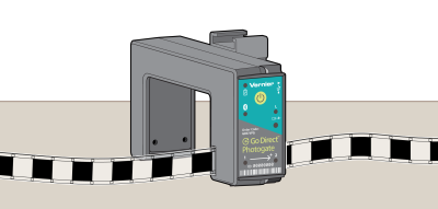
Sitting on the photogate arms
Mounted on a ring stand using the included accessory rod
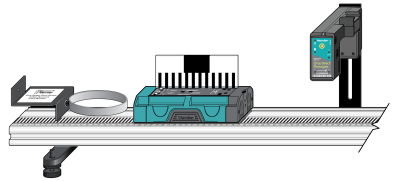
Mounted on a dynamics track using a photogate bracket
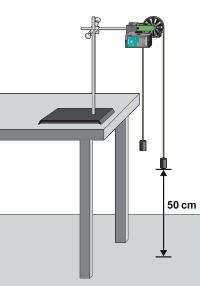
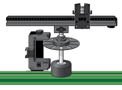
Mounted on a ring stand with a pulley and included accessory rod
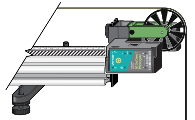
Mounted on a dynamics track using a pulley and pulley bracket
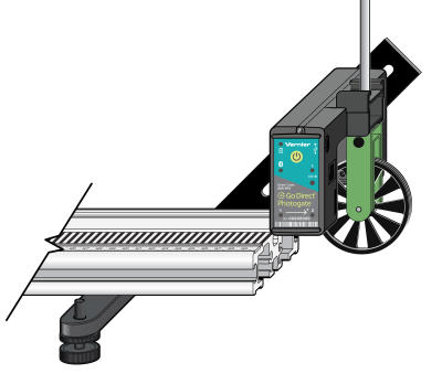
Mounted on a dynamics track using a photogate bracket and pulley
Used with photogate bar tape
Mounted on the original Centripetal Force Apparatus
Specifications
|
Infrared source |
Peak at 880 nm |
|
Gate width |
77.5 mm |
|
Internal gate separation |
20 mm |
|
Distance from internal gates to bottom of photogate arms |
~10 mm |
|
Distance from internal gates to sides of photogate arms |
~5 mm |
|
Gate 1, Gate 2, and Laser Gate LED indicators |
Off for unblocked gate On for blocked gate |
|
Battery |
650 mAh Li-Poly Rechargeable |
|
Battery life (single full charge) |
~10 hours continuous data collection |
|
Battery life (long term) |
~300 full charge cycles (several years depending on usage) |
Safety
Laser Safety Note: When using the Laser Gate mode, do not align the external laser gate by sighting by eye. Follow all safety precautions indicated by the laser manufacturer.
Care and Maintenance
Battery Information
Go Direct Photogate contains a small lithium-ion battery. The system is designed to consume very little power and not put heavy demands on the battery. Although the battery is warranted for one year, the expected battery life should be several years. Replacement batteries are available from Vernier (order code: GDX-BAT-650).
Storage and Maintenance
To store Go Direct Photogate for extended periods of time, put the device in sleep mode by holding the button down for at least three seconds. The red LED will stop flashing to show that the unit is in sleep mode. Over several months, the battery will discharge but will not be damaged. After such storage, charge the device for at least two hours, and the unit will be ready to go.
Exposing the battery to temperatures over 35°C (95°F) will reduce its lifespan. If possible, store the device in an area that is not exposed to temperature extremes.
Water Resistance
Go Direct Photogate is not water resistant and should never be immersed in water.
If water gets into the device, immediately power the unit down (press and hold the power button for more than three seconds). Disconnect the sensor and charging cable, and remove the battery. Allow the device to dry thoroughly before attempting to use the device again. Do not attempt to dry using an external heat source.
How the Sensor Works
The sensor has infrared LED emitters on one arm and photodiodes on the other arm. An object blocks the infrared beam as it passes through the gates. Times associated with the photodiode state-changes are used to calculate motion data for the objects.
For a good discussion of how photogates work in general, see “Photogates: An instrument evaluation,” Eugene P. Mosca and John P. Ertel, Am. J. Phys. 57 (9), 840–844 (1989).
Troubleshooting
For troubleshooting and FAQs, see www.vernier.com/til/4197
Repair Information
If you have followed the troubleshooting steps and are still having trouble with your Go Direct Photogate, contact Vernier Technical Support at support@vernier.com or call 888-837-6437. Support specialists will work with you to determine if the unit needs to be sent in for repair. At that time, a Return Merchandise Authorization (RMA) number will be issued and instructions will be communicated on how to return the unit for repair.
Accessories/Replacements
| Item | Order Code |
|---|---|
|
PF |
|
|
PF-CART |
|
|
SPA |
|
|
TAPE |
|
|
LASER |
|
|
STAND |
|
| Go Direct Photogate Timing Cable |
VPG-CB-GDX |
| Go Direct Time of Flight Pad Cable |
TOF-CB-GDX |
|
TOF-VPL |
|
|
GDX-BAT-650 |
|
|
CB-USB-MICRO |
|
|
CB-USB-C-MICRO |
|
|
ACC-ROD |
Warranty
Warranty information for this product can be found on the Support tab at www.vernier.com/gdx-vpg/#support
General warranty information can be found at www.vernier.com/warranty
Disposal
When disposing of this electronic product, do not treat it as household waste. Its disposal is subject to regulations that vary by country and region. This item should be given to an applicable collection point for the recycling of electrical and electronic equipment. By ensuring that this product is disposed of correctly, you help prevent potential negative consequences on human health or on the environment. The recycling of materials will help to conserve natural resources. For more detailed information about recycling this product, contact your local city office or your disposal service.
Battery recycling information is available at www.call2recycle.org
Do not puncture or expose the battery to excessive heat or flame.
 The symbol, shown here, indicates that this product must not be disposed of in a standard waste container.
Contact Support
Fill out our online support form or call us toll-free at 1-888-837-6437.