Use our sensor pinout information when building your own sensors to work with our interfaces or when you want to use our sensors with your own A to D converters.
British Telecom Analog (Right Hand)
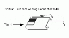
Pinout
- Pin 1 = ±10 Volt – Sensor Output
- Pin 2 = Ground
- Pin 3 = Resistance Reference (Vres)
- Pin 4 = Auto Identify
- Pin 5 = Power (+5 Volts DC)
- Pin 6 = 0-5 Volt – Sensor Output
British Telecom Digital (Left Hand)
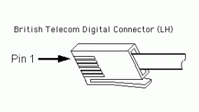
Pinout
- Pin 1 = Digital I/O
- Pin 2 = Digital I/O
- Pin 3 = Auto Identify
- Pin 4 = Power (+5.3 Volts)
- Pin 5 = Ground
- Pin 6 – Digital I/O
Resources
- Sensor-Specific Pinouts
- Motion Detector ⚊ Pin 1 = Echo Input, Pin 2 = Initiate Signal
- Photogate ⚊ Pin 1 = Input Signal
- Radiation Monitor ⚊ Pin 1 = Input Counter
- Rotary Motion ⚊ Pin 1 = CCW counter, Pin 2 = CW counter, Pin 6 – X4 Resolution
- Digital Protoboard Adapter (
BTD-ELV ) - Breadboard Cable (Digital) (
BB-BTD ) - Where can I find BTA and BTD connectors and sockets?
- How do I know which color wire connects to which pin on the BTA/BTD connector?
5-Pin DIN
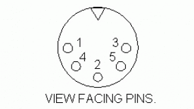
Pinout
- Pin 1 = 0 – 5 Volt Sensor Output
- Pin 2 = Unused
- Pin 3 = Auto Identify
- Pin 4 = Power (+5 Volt DC)
- Pin 5 = Ground
Resources
- DIN to BTA Adapter (
DIN-BTA )
8-Pin DIN
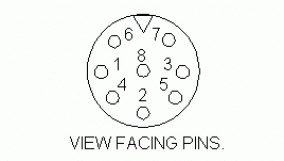
Pinout
- Pin 1 = 0-5 Volt Sensor Output
- Pin 2 = Unused
- Pin 3 = Auto Identify
- Pin 4 = Power (+5 Volt DC)
- Pin 5 = Ground
- Pin 6 = Power (+12 Volt DC)
- Pin 7 = Power (-12 Volt DC)
- Pin 8 = DAC
Resources
1/4″ Stereo Jack
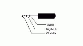
Pinout
- Tip = Power (+5 Volt DC)
- Middle = Digital Input
- Bottom = Sheild
Resources
RJ-11/RJ-12 Sockets (US Phone Jack)
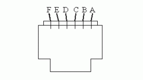
Pinout
- Pin A =
- Pin B =
- Pin C =
- Pin D =
- Pin E =
- Pin F =
Resources
| Photogate (VPG-BTD) |
Interface (VPL-all) |
Accessories (GDX-PL/VPL) |
Ext. Switch (VPL-old) |
Aux Port (VPL-old) |
|
|---|---|---|---|---|---|
| Pin A (leftmost pin in socket) |
Unused | Ground | Ground | Ground | Gate B – output, Aux input |
| Pin B | Power | Power | Power | Power | Gate B output inverted |
| Pin C | Output Signal |
Output Signal |
Gate A output inverted | Switch Input | Gate A output, Aux Input |
| Pin D | Ground | Ground | Gate A output, Aux Input | Ground | Gate A output inverted |
| Pin E | Auto Identify |
Auto Identify |
Gate B output inverted | Switch Input | Ground |
| Pin F (rightmost pin in socket) |
Unused | Ground | Gate B – output, Aux input | Ground | Power |
