A half-Atwood machine, with a cart, string, pulley, and hanging mass, is a common Newton’s Second Law and kinematics lab. If you have a pulley and photogate in this setup, you can easily collect position, velocity, and acceleration data.
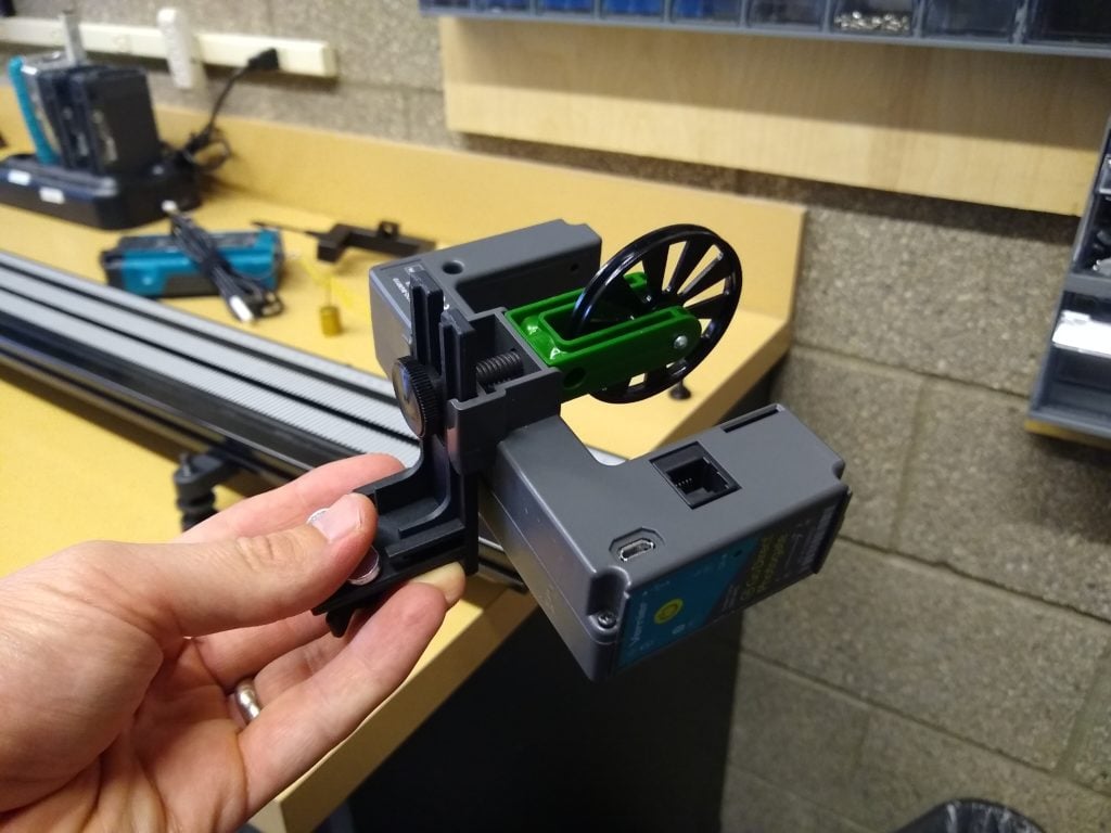
Starting in 2016, the Pulley Bracket (B-SPA) includes a special attachment for the Photogate (VPG-BTD). The image below shows how to configure the Pulley Bracket with this special attachment with the Photogate.
The following video demonstrates how to attach the Pulley Bracket, Photogate, and Ultra Pulley to the track.
Some details to note:
- The Pulley Bracket comes with two thumb screws. When attaching both a photogate and the Ultra Pulley use the longer thumb screw. If you are only attaching the Ultra Pulley, use the shorter thumb screw.
- The Pulley Bracket slot allows you to adjust the height of the Ultra Pulley above the top surface of the track. If you are using the photogate/pulley in a half-Atwood setup, lower the Ultra Pulley to a position where the string – connected to the cart on one end and a hanging mass on the other – is parallel to the track; in that position, the force exerted by the string is horizontal, i.e. does not have a vertical component.
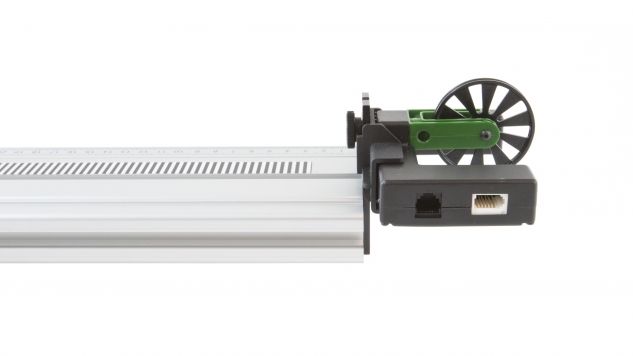
If you have a Go Direct® Photogate (GDX-VPG), you’ll find the process a bit easier because the Go Direct Photogate was designed with the pulley bracket in mind, the extra attachment for a photogate was molded into the sensor.
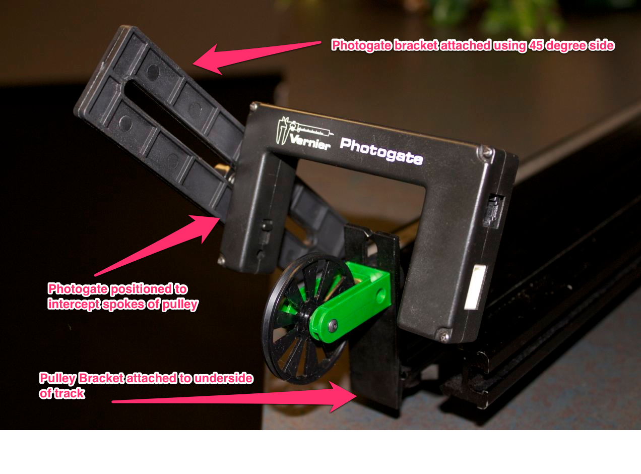
Prior to the 2016 update to the Pulley Bracket, students used the Photogate Bracket (PGB-VDS) to align the photogate beam with Ultra Pulley. The Photogate Bracket has two sides with different tabs. One side is configured for a vertical position for supporting a photogate over the track surface. The other side has tabs for a 45 degree position.
It is this 45-degree position that allows you to easily support a photogate so that it can read the motion of a pulley.
This image shows how to configure the bracket.