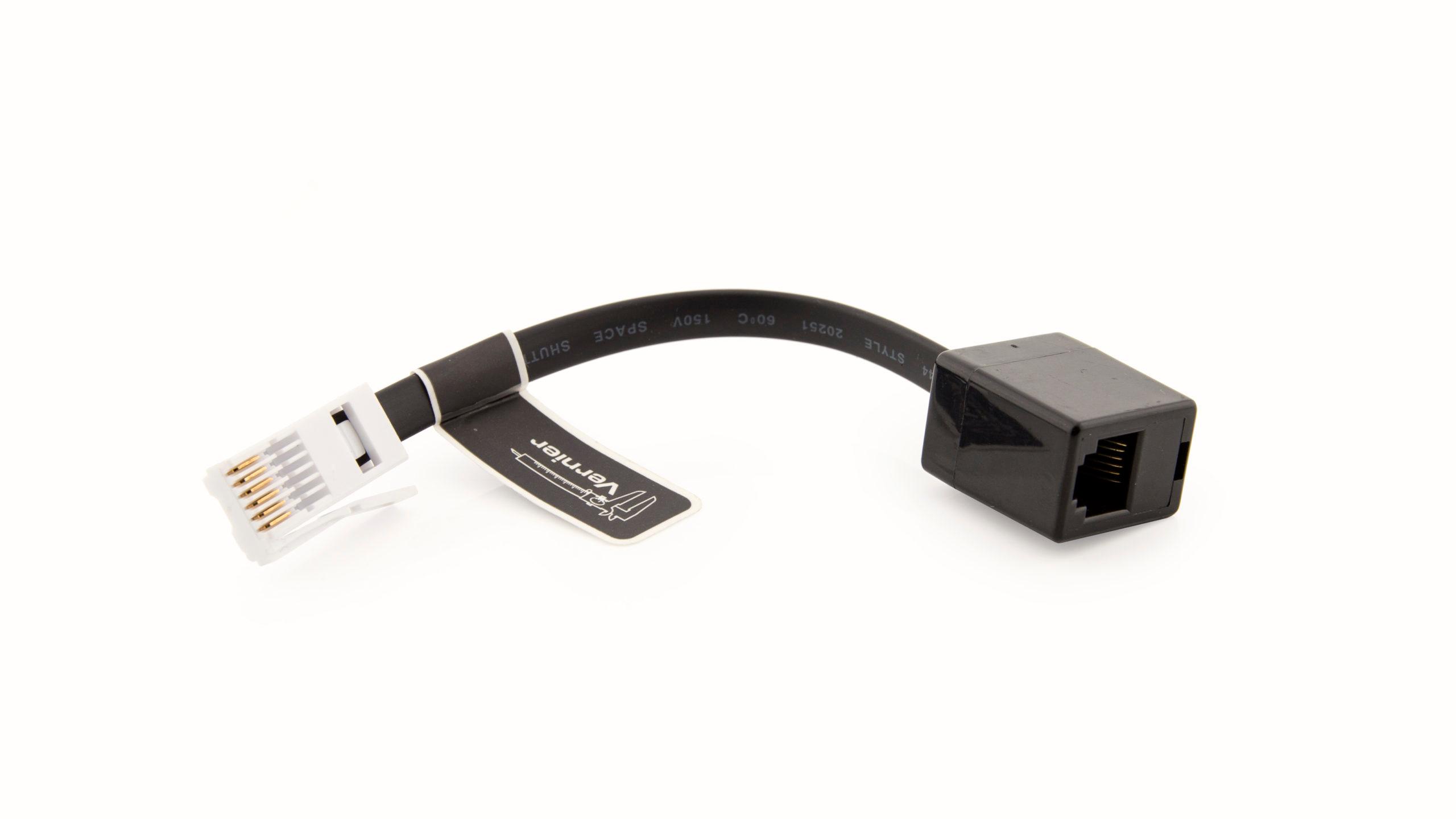
Rotary Motion Sensor
The Vernier Rotary Motion Sensor is a bidirectional angle sensor designed to measure rotational or linear position. It is commonly used to study rotational dynamics, angular momentum, and the period of a pendulum. It produces a pulse on one digital line when it rotates one direction and on another line when it rotates in the other direction. To keep track of the motion of the Rotary Motion Sensor, you can simply tally pulses in each direction.
The Rotary Motion Sensor should be connected to the Digital 1 port on the Vernier Arduino Interface Shield or a Digital Protoboard Adapter wired to Arduino pins 2, 3, 4, and 5 as explained in the Connecting Vernier Sensors to the Arduino Using a Breadboard section. The VernierLib library does not support the Rotary Motion Sensor, but the sample sketch, VernierTutorialRotaryMotion, tallies the motions in both directions and reports the result every half second.
The pulses that the Rotary Motion Sensor generates are very short. To detect and count them accurately, you need to use “interrupt lines.” Using an interrupt frees the microcontroller to do other tasks while not missing an input from the rotary encoder. (For more information on Arduino interrupts see: http://arduino.cc/en/Reference/AttachInterrupt)
It is useful to know that the Vernier Rotary Motion Sensor can take data in either of two modes. In Normal resolution mode, it measures an angle to the nearest degree. In High-Resolution mode, the Rotary Motion Sensor measures an angle to one quarter of a degree. The VernierTutorialRotaryMotion sketch defaults to Normal resolution, but you can switch to High-Resolution by changing the variable highResOn to True.
/* VernierTutorialRotaryMotion (v2017) * This sketch monitors a Vernier Rotary Motion Sensor and * returns angle readings every half second. The default * mode is Normal resolution (1 deg angle changes), but you * can switch to High resolution (0.25 deg angle changes). * * Plug the Rotary Motion Sensor into the Digital 1 port on the * Vernier Arduino Interface Shield or into a Digital Protoboard * Adapter wired to Arduino pins 2, 3, 4, and 5. */ boolean highResOn = false; //create global variable for resolution mode (normal=false, high=true) float angleChange; //create global variable for angle measurement const int encoderPinCCW = 2; //create global variable for pin assignment counterclockwise direction const int encoderPinCW = 3; //create global variable for pin assignment clockwise direction const int resPin = 5; //create global variable for pin assignment for resolution mode volatile int encoderPos = 0; //create global variable for position (variables changed within interrupts are volatile) void setup() { Serial.begin(9600); //setup communication to display pinMode(encoderPinCCW, INPUT_PULLUP); //setup CCW pin pinMode(encoderPinCW, INPUT_PULLUP); //setup CW pin pinMode (resPin, OUTPUT); //setup pin for resolution mode if(highResOn) angleChange = 0.25; //check if high resolution is true (angle=0.25 deg) else angleChange = 1; //set normal resolution angle to 1 deg digitalWrite(resPin,highResOn); //initialize resolution mode digitalWrite(encoderPinCCW, LOW); //initialize CCW pin status digitalWrite(encoderPinCW, HIGH); //initialize CW pin status attachInterrupt(digitalPinToInterrupt(encoderPinCCW), doEncoderCCW, RISING); //trigger when pin goes from LOW to HIGH attachInterrupt(digitalPinToInterrupt(encoderPinCW), doEncoderCW, FALLING); //trigger when pin goes from HIGH to LOW } void loop() { Serial.println(encoderPos*angleChange); //display angle in degrees delay(500); //wait half second } void doEncoderCCW() { //create function to measure CCW angle change encoderPos++; //count UP } void doEncoderCW() { //create function to measure CW angle change encoderPos--; //count DOWN }
Previous
Drop CounterContents
Introduction- Arduino Terminology
- About Vernier Sensors: Analog (BTA) and Digital (BTD)
- Connecting Vernier Sensors to Arduino
- Using the VernierLib Library
- Using Vernier Analog (BTA) Sensors with Arduino
- Using Vernier Digital (BTD) Sensors with Arduino
- Using the Vernier Digital Control Unit (DCU) with Arduino
- Displaying Sensor Data on an LCD Screen
- Using Motors with Arduino
- Calibrating Vernier Analog Sensors
- Importing Data into Graphical Analysis 4
- Importing Data into Logger Pro®
- Projects and Ideas
- Turn on a Buzzer Based on a Motion Detector Reading
- Produce a Tone Out that Depends on Sensor Reading
- Controlling a RGB LED with a 3-Axis Accelerometer
- Controlling a Mousetrap with a Photogate
- Laser Pointer Controlled by a Motion Detector
- Add a Display For Temperature Readings
- Auto-ID for Digital (BTD) Sensors
- Auto-ID for Analog (BTA) Sensors with Display
- Pendulum Driver
- Levitating Ping Pong Ball
- DCU-Controlled Birthday Candle
- Controlling a Robotic Hand
Vernier Engineering Contest
Vernier recognizes instructors for creative uses of Vernier sensors to introduce engineering concepts and/or practices. Vernier Engineering Award »