Combining the power of LabVIEW software with the flexibility of our wireless Go Direct sensors opens the door to engaging coding projects and unique monitoring applications. On our website, you can find free LabVIEW code that can help you and your students incorporate Go Direct sensors into custom LabVIEW programs.
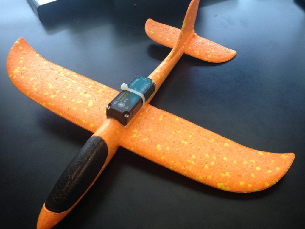
A nice example of combining LabVIEW with Go Direct sensors is a program that determines the pitch and roll of a toy airplane using the readings from Go Direct Acceleration.

Go Direct Acceleration offers 11 sensor channels, including a 3-axis gyroscope and a 3-axis acceleration sensor. Pitch and roll (tilt angle) can be calculated using the 3-axis gyroscope and integrating the angular velocity readings over time or by using the 3-axis accelerometer sensor readings to determine the orientation of the gravity vector.
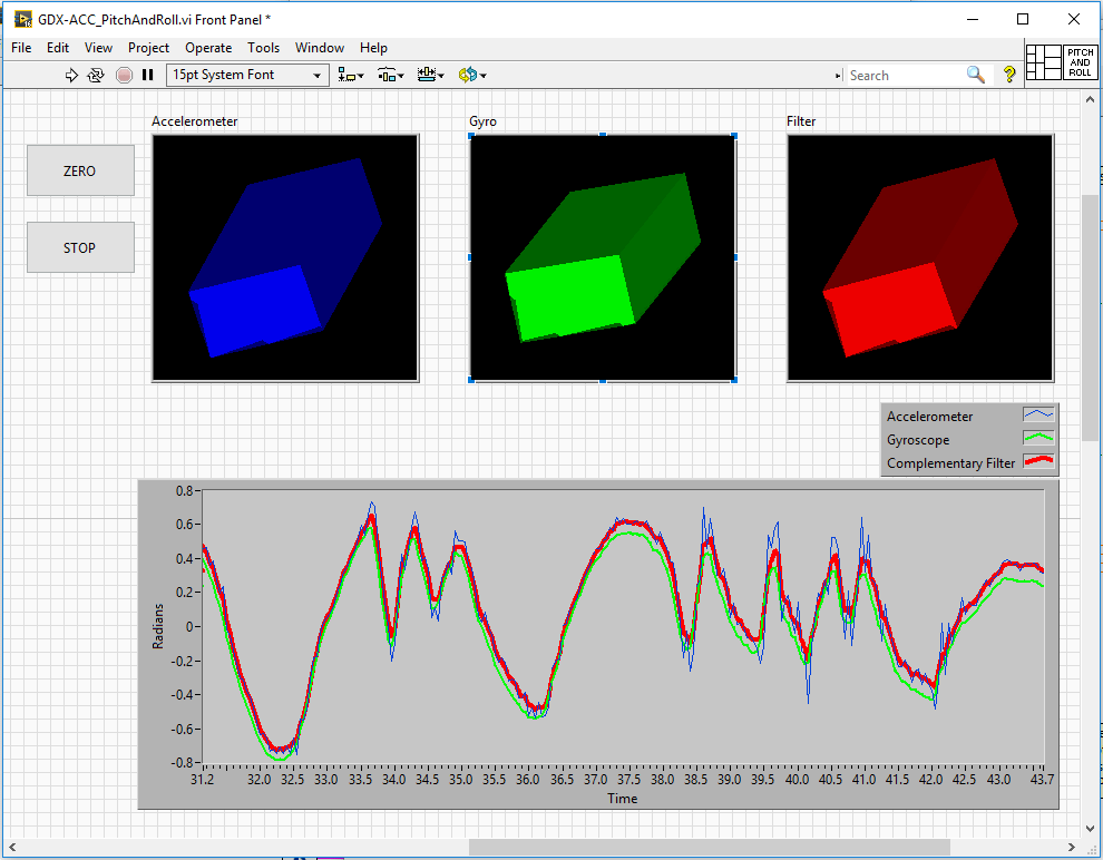
The gyroscope responds quickly and accurately as the sensor is rotated, providing a good indicator of tilt in dynamic conditions. However, there is a small amount of drift in the sensor when it is in a static condition, and when dealing with integration over time, even the smallest offset will cause the integrated data to grow to infinity. In contrast, the accelerometer will provide good tilt results in static conditions, but will have a lot of noise from the rapid movement of the object, resulting in short-term fluctuations. A common method of calculating pitch and roll is to combine the strengths of both sensors using a complementary filter, which can be done in LabVIEW.

In our LabVIEW program we use a 3D picture control to represent the orientation of the sensor. It’s easy to see in the chart how the filtered signal (red) minimizes the noise of the accelerometer (blue) during the fast changes and the drift of the gyroscope (green) over slower changes.
