Sharing ideas and inspiration for engagement, inclusion, and excellence in STEM
After 30 years of teaching science at East Palestine Schools in Ohio, Dr. Lisa Bircher is confident about one thing: students deserve to be involved in experiences that expand beyond the classroom. Whether that’s monitoring water quality in local streams and lakes with probeware or simply sorting through recyclables in the outdoor area behind the school property, students learn best when they are actively engaged in real-world, hands-on learning opportunities.
Bircher earned the 2023 NABT Ecology/Environmental Science Teaching Award, sponsored by Vernier Science Education, and recently made the transition into retirement. As part of her plans for the future, Bircher is exploring going into ministry, laughing, “It’s a lot like teaching, honestly. I just don’t have the really cool lab equipment.”
Hands-On Learning Helps Students Connect Data with Real-World Phenomena
Bircher, who has taught high school biology, human physiology, and environmental science, as well as seventh grade life science and physical science, believes that giving students the opportunity to explore phenomena firsthand helps ground scientific inquiry in the natural curiosity of students. They get to watch, touch, feel, or smell something new, make guesses about it, and see how those hypotheses play out in real time.
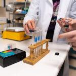
“I always feel like it’s important to start with a real-life experience in the classroom. Even if it’s something basic—like taking a hand lens and observing the shape of a crystal in a physical science classroom, or putting yeast in an Erlenmeyer flask with different materials to observe the CO2 output during cellular respiration—it gets the students engaged.”
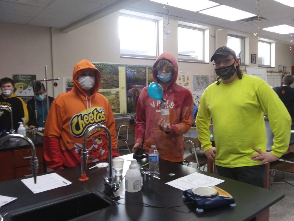
Image provided by East Palestine Schools.
Starting with activities like these, Bircher explains, helps students to develop a sense of connection and investment before moving into the more challenging aspects where they might need more teacher support, including data analysis.
“Getting hands-on first is really important. But it was also really valuable to go through the data together after an activity to help make sure students actually understand the data set and what it means in relation to what they just observed.”
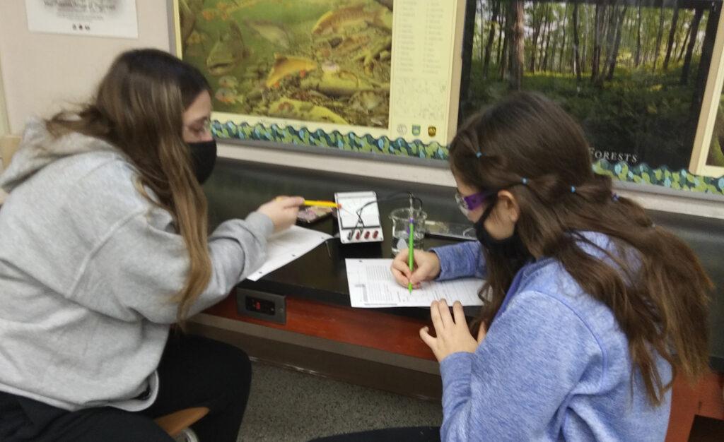
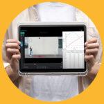
Developing scientific literacy in graphs and data visualization is a skill that Bircher feels is particularly key for students. “It was such a big part of my teaching career, helping students gain confidence in basic organization of scientific information that would be meaningful when read by another student or teacher,” Bircher emphasizes. “It’s something students have to develop through practice, whether that’s drawing out graphs and tables by hand or generating them in real time with software like Vernier Graphical Analysis®.”
“Science is a lot like learning a new language.” Bircher says. “And the learner must use science in their life experience to become truly proficient.”
Connection to Place and People Is a Powerful Learning Tool
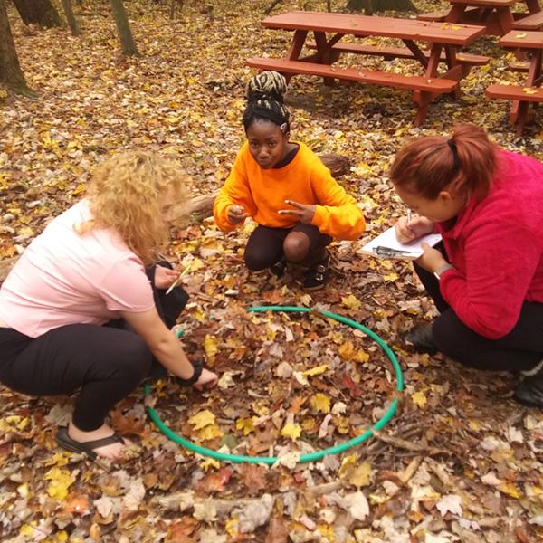
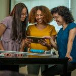
Together with fellow East Palestine educator Bonnie Sansenbaugher, Bircher founded OASIS (Outdoor Area for Studies in Science) in 2015—a dedicated outdoor classroom for staff, students, and the community to use for science classes, camps, and clubs. OASIS, which is adjacent to East Palestine School, consists of 48 acres of woods, open meadows, trails, and a pond, as well as picnic tables and an amphitheater. Bircher and Sansenbaugher wanted an accessible and authentic way for students to be able to connect with the natural world in the context of science education.
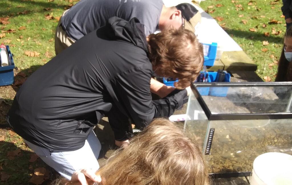
Image provided by East Palestine Schools.
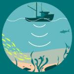
Initially conceived by Bircher and Sansenbaugher as a home for their science club, OASIS gives students the opportunity to explore their own backyard through the lens of science. For example, in one excursion, students collected data from the local pond to evaluate the health of their water systems using probeware to collect pH, dissolved oxygen, temperature, turbidity, conductivity, and chlorophyll levels and then compared their data to other locales posted online. Bircher says her students felt a deep sense of inspiration and satisfaction knowing that they were making a difference in their own community, whether that’s examining the health of their aquatic ecosystems, removing invasive plant species like garlic mustard plants, or collecting and quantifying trash cleanup.
Encouraging Students to Make a Difference through Service Learning
For many years, OASIS was also home to the Science Camp, a summer day camp held for students
K–4 mentored by high school students. Not only were students getting the chance to spend time outdoors, but the high school volunteers got to exercise service-learning as mentors.
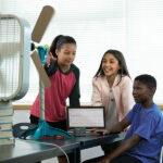
“We had some core student involvement from really motivated and inspired high schoolers who were able to teach through their leadership. They planned the lessons, refined and practiced camp activities, prepared all the materials, and implemented those plans they designed themselves. We would do a day of fossils, a day looking at plants, or learning about recycling. As teachers, we’d support in the background. It worked out so well, it was great.”

Image provided by East Palestine Schools.
Both Bircher and Sansenbaugher underscore how programs like the Science Camp not only helped inspire student interest in science, but they also built strong connections across student levels and in the greater community: “We found that our place-based efforts and dedication to service-learning is of the utmost importance. We noticed that students are more willing to volunteer and commit to community service as a result of mentoring at Science Camp.”
Meaningful environmental stewardship involves both an interest and commitment to science learning as well as a feeling of connection with your community. Bircher concludes, “As a science teacher, I’m not only trying to encourage a better appreciation for science in my students, but also a better appreciation for who they are and for what they can do in their future.”
Looking for biology or environmental science tools to help your students explore the outdoors?
Check out our resources! Questions? Reach out to biology@vernier.com or call 888‑837‑6437.
Share this Article
Related Articles

Sign up for our newsletter
Stay in the loop! Beyond Measure delivers monthly updates on the latest news, ideas, and STEM resources from Vernier.