This is associated with the original version of Force Plate (
If the cable is damaged on a Force Plate, it can be replaced with an Analog BTA Cable (
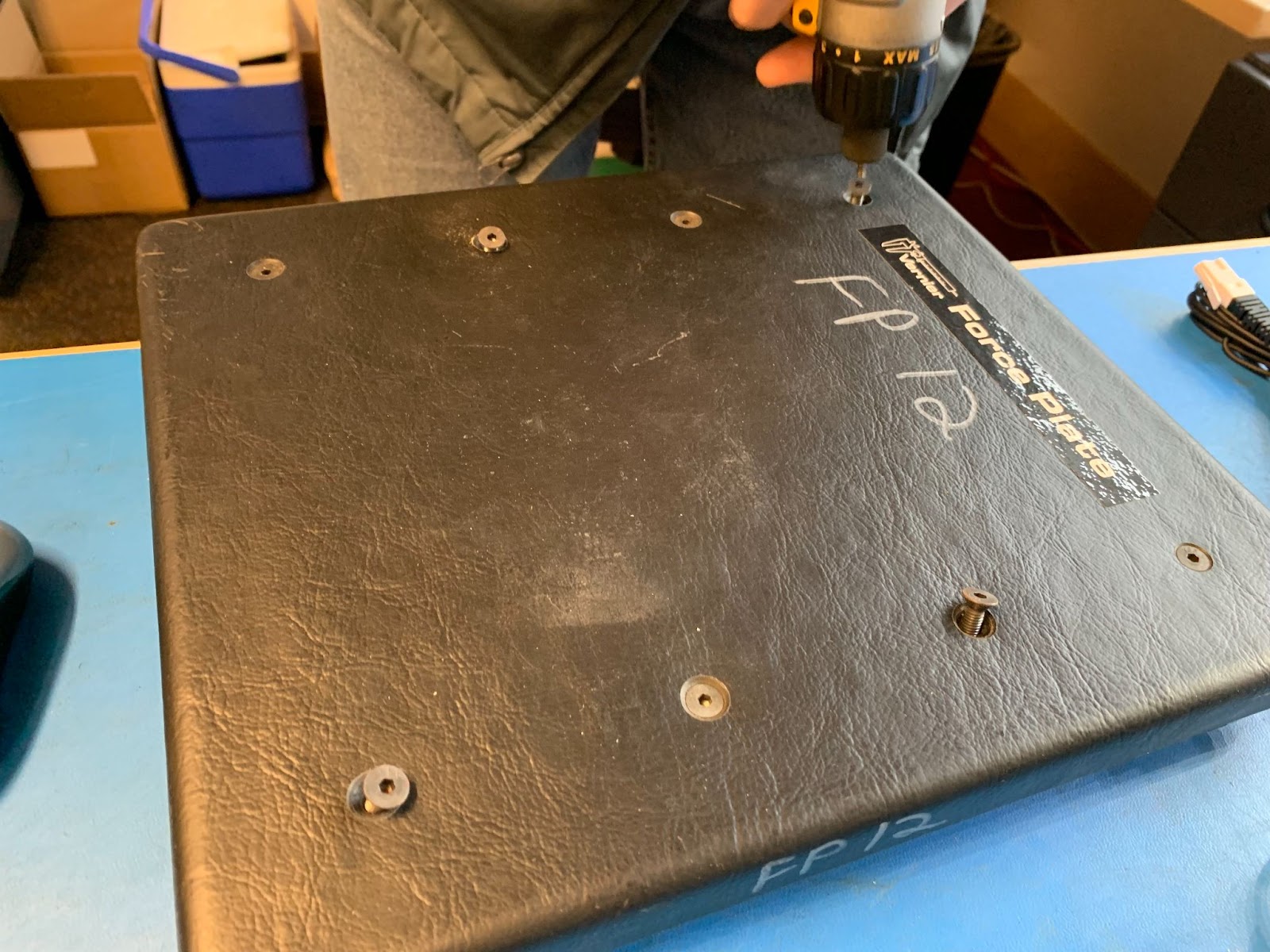
- Use a ⅛” hex key to remove the screws from the top of the force Plate. Alternate sides as you remove each screw. Take care not to strip the screws.
Note: There is no need to remove the silver screws on the bottom of the plate. - Remove the top of the Force Plate. There are two separate pieces that will both lift straight up.
- With a soldering iron, heat each of the 5 connection points for the wires enough to remove them.
- Using pliers, remove the strain relief that holds the cable into the body of the plate. This may take some muscle and wiggling back and forth to get it out. Do not destroy the strain relief. You will need it on the new cable.
- Remove the old cable.
- Slide the strain relief onto the new cable and put it in place. Note the hole is not round, so the strain relief needs to be in the correct orientation.
- Solder the wires in place, taking note of the order of the colors. The wires are fairly thin, so take care not to overheat them.
Note: The colors of the wires in your replacement cable may not be the same as the original. To make sure you connect the right wire to the right location, do a continuity check. The colors in the photo shown are:
Pin 1 is not next to the keyPIN 1 – NC (NO CONNECTION)
PIN 2 – GND (GROUND)
PIN 3 – GREEN
PIN 4 – BROWN
PIN 5 – ORANGE
PIN 6 – RED
A diagram of the BTA connector and pins are shown in: Vernier Wired Sensor Pinouts - Replace the top of the plate. Do not over-tighten the screws, and take care to alternate the order in which they are tightened.


Related articles:
How do I replace the load cells in a Force Plate (order code FP-BTA)?
Force Plate Troubleshooting and FAQs