The AUX port and corresponding Auxiliary Voltage sensor channel are intended to provide support for future accessories. The Auxiliary Voltage sensor channel reports raw voltage (0 to 5 V) from a device connected to the AUX port.
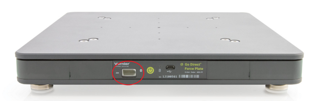
About the AUX Port
The AUX port uses a British Telecom Analog connector, which is the same connector used for analog sensors on Vernier interfaces (e.g., Go!Link, LabQuest Mini, and LabQuest 3). The AUX port is wired to provide power to a connected sensor, making it possible to use the port to collect raw voltage data from most Vernier analog (BTA) sensors.
AUX Port Pinout
- Pin 1 – Unused
- Pin 2 – Ground
- Pin 3 – Unused
- Pin 4 – Unused
- Pin 5 – Power out (+5V DC)
- Pin 6 – 0 to 5V signal input
- The AUX port does not use Pins 3 or 4 (used for sensor identification) and cannot automatically identify a connected sensor.
- The AUX port does not use Pin 1 (±10V signal input) and does not work with sensors that use that line for data output, such as the ±10V Voltage Probe (
VP-BTA ) and the 30-Volt Voltage Probe (30V-BTA ). - The Go Direct Force Plate will only supply power to the AUX Port when the Auxiliary Voltage sensor channel has been selected in the Graphical Analysis or LabQuest App.
About the Auxiliary Voltage Sensor Channel
The Auxiliary Voltage sensor channel is only available when the Go Direct Force Plate’s User Profile is configured for Physics. If the list of sensor channels does not include the Auxiliary Voltage channel, you will need to reconfigure your Go Direct Force Plate. For instructions, see
How do I switch between Physics and Physiology Sensor Channels on my Go Direct Force Plate?
Sensor Channel Details
- The sensor channel reports raw voltage data (0 to 5 V) from a sensor or other device connected to the AUX port.
- Raw voltage data from a sensor can be converted to more typical sensor readings using a sensor’s calibration equation as the expression in a calculated column. (Sensor calibration equations can be found in the sensor’s user manual.)
- There is no power provided to the AUX port unless the Auxiliary Voltage sensor channel is selected.
Sample Idea for using the Aux Port
You can use your imagination to think of ways to use this channel. For example, use a Hand Dynamometer (
- Connect the Hand Dynamometer to the AUX port on the Go Direct Force Plate.
- Launch your data collection app (Graphical Analysis or LabQuest App).
- Adjust the sensor channels to use both Force and Auxiliary Voltage.
- Stand on the force plate and hold the Hand Dynamometer so that one side with the rubber grip is against the wall as you push against the other side.
- Collect your data.
- The Force channel collects force data normal to the surface of the Go Direct Force Plate.
- The Auxiliary Voltage channel collects a raw voltage data related to the force (normal to the surface of the wall) that you are pushing on the wall.
- Create a calculated column for the Wall Force (measured in Newtons) using the calibration equation for a Hand Dynamometer: Wall Force (N) = 176.833 * “Auxiliary Voltage” – 19.506