Shop
- Engineering
- Arduino
- Using Vernier Sensors with Arduino Guide
- Projects and Ideas
- Auto-ID for Digital (BTD) Sensors
Auto-ID for Digital (BTD) Sensors
This is simple sketch showing how AutoID can be used with Vernier digital (BTD) sensors. Most Vernier BTD sensors have a fixed resistor which is used to identify the type of sensor. After the sensor is identified the sketch displays the sensor name.
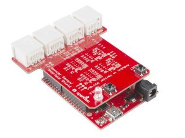
This sketch works with the SparkFun Vernier Interface Shield. To use this sketch with a system you wire yourself with one BTD adapter on a on a breadboard, the AutoID pin of the BTD adapter (pin 3) needs to be connected to pin A5 of the Arduino.
AutoID with multiple sensors: To make the AutoID system work for more than one adapter requires more complex electronics. The SparkFun Vernier Interface Shield contains a multiplexer and it can handle autoID on two BTA and two BTD sensors in one sketch.
This is simple sketch showing how AutoID can be used with Vernier digital (BTD) sensors. Most Vernier BTD sensors have a fixed resistor which is used to identify the type of sensor. After the sensor is identified the sketch displays the sensor name.
This sketch works with the SparkFun Vernier Interface Shield or a BTD socket wired via a breadboard.
AutoID with multiple sensors will work with the SparkFun Vernier Interface Shield, but to make the AutoID system work for more than one BTD connector, using one sketch, requires added electronics.
/*
VernierDigitalAutoID (v 2014.12)
Reads the information to AutoID a Vernier BTD sensor with resistor ID.

When used with the SparkFun Vernier Interface Shield, this program will AutoID
two different sensors on BTD1 and BTD2. With homemade, breadboard
connections, it will work with only one sensor.

After the AutoID, assuming Vernier analog (BTD) Sensors are connected to the BTD connectors,
this sketch displays the name of the sensor and the units. This sketch does not read data
because there are several different types of readings that can be done with digital sensors
(distance measurements, radiation counts, photogate timing, etc). Instead, this sketch
will name the Vernier Arduino sketch to use to read that sensor. For example, if you connect
a Motion Detector, it will suggest the VernierMotionDetector program.

 See www.vernier.com/arduino for more information.
*/
int ReadingNumber;
int Channel; //BTA (Channel 1 or 2) or BTD connector (Channel 3 or 4)
float VoltageID[5];
int led =13;
int SensorNumber[5]; //integer indicating sensor number'
String Name[5];
String ShortName[5];
String Units[5];
float Intercept[5];
float Slope[5];
int Page[5];
int (CalEquationType[5]);
float VCC= 5.00;// "5 volt" power supply voltage used in resistor ID section
void setup()
 {
    int muxlsb = 10; //low byte of multiplexer
    int muxmsb = 11; //high byte of multiplexer
    Serial.begin(9600);
    pinMode(led, OUTPUT); //LED on SparkFun Vernier Shield
    digitalWrite(led, LOW);
    pinMode(muxlsb, OUTPUT);
    pinMode(muxmsb, OUTPUT);
    Serial.println("");
    //Read BTD1 Sensor:
    digitalWrite(muxlsb, LOW); //set multiplexer for BTD1
    digitalWrite(muxmsb, HIGH);
    Channel=3;
    BTDResistorSensorID(Channel);
    PrintSensorInfo();// this line can be commented out if you do not need all this info !!!
    //Read BTD2 Sensor
    digitalWrite(muxlsb, HIGH); //set multiplexer for BTD2
    digitalWrite(muxmsb, HIGH);
    Channel=4;
    BTDResistorSensorID(Channel);
    PrintSensorInfo();// this line can be commented out if you do not need all this info !!!
  }

void loop()
  {
  }

void BTDResistorSensorID(int Channel)
   {
      Name[Channel]="";// clear name string
      ShortName[Channel]="";// clear name string
      SensorNumber[Channel] = 0;
      delay (10);
      int CountID = analogRead(A5);
      VoltageID[Channel] = CountID / 1023.0 * VCC;// convert from count to voltage
      if (VoltageID[Channel]>3.27 & VoltageID[Channel]<3.61) SensorNumber[Channel] = 2; //Motion Detector
      if (VoltageID[Channel]>4.45 & VoltageID[Channel]<4.46) SensorNumber[Channel] = 3; //motion not used
      if (VoltageID[Channel]>3.80 & VoltageID[Channel]<3.88) SensorNumber[Channel] = 4;  //photogate
      if (VoltageID[Channel]>4.08 & VoltageID[Channel]<4.16) SensorNumber[Channel] = 5; //Drop Counter
      if (VoltageID[Channel]>4.32 & VoltageID[Channel]<4.40) SensorNumber[Channel] = 6; //rotary
      if (VoltageID[Channel]>4.50 & VoltageID[Channel]<4.59) SensorNumber[Channel] = 7;//Radiation Monitor
      if (VoltageID[Channel]>4.45 & VoltageID[Channel]<4.46) SensorNumber[Channel] = 8; //DCU - 1st generation
      if (VoltageID[Channel]>1.52 & VoltageID[Channel]<1.70) SensorNumber[Channel] = 9; //DCU - 2nd generation
      if (VoltageID[Channel]>1.18 & VoltageID[Channel]<1.30) SensorNumber[Channel] = 10; //Polarimeter
      if (VoltageID[Channel]>0.86 & VoltageID[Channel]<0.95) SensorNumber[Channel] = 11;   //Projectile Launcher
      if (VoltageID[Channel]>0.62 & VoltageID[Channel]<0.68) SensorNumber[Channel] = 12; //Linear Translator for DAK
      if (VoltageID[Channel]>0.43 & VoltageID[Channel]<0.48) SensorNumber[Channel] = 13; //Motion Encoder
      if (VoltageID[Channel]>4.64 & VoltageID[Channel]<4.73) SensorNumber[Channel] = 14; // possible digital sensor
      switch (SensorNumber[Channel])
         {
            case 2:
                  Name[Channel] = "Motion - Position" ;
                  Units[Channel] = "Use VernierMotionDetector" ;
                  ShortName[Channel] = "Position";
                  Slope[Channel]=1;
                  Intercept[Channel]=0;
                  Page[Channel] = 1;; //calibration storage page
                  CalEquationType[Channel]=1;
            break;
            case 3:
                  Name[Channel] = "Motion -NU" ;
                  Units[Channel] = "not used" ;
                  ShortName[Channel] = "Motion -NU";
                  Slope[Channel]=1;
                  Intercept[Channel]=0;
                  Page[Channel] = 1;; //calibration storage page
                  CalEquationType[Channel]=1;
            break;
            case 4:
                  Name[Channel] = "Photogate" ;
                  Units[Channel] = "Use VernierPhotogate" ;
                  ShortName[Channel] = "PG";
                  Slope[Channel]=1;
                  Intercept[Channel]=0;
                  Page[Channel] = 1;; //calibration storage page
                  CalEquationType[Channel]=1;
            break;
            case 5:
                  Name[Channel] = "Drop Counter" ;
                  Units[Channel] = "Use VernierCount" ;
                  ShortName[Channel] = "Drop Count";
                  Slope[Channel]=1;
                  Intercept[Channel]=0;
                  Page[Channel] = 1;; //calibration storage page
                  CalEquationType[Channel]=1;
            break;
            case 6:
                  Name[Channel] = "Rotary Motion" ;
                  Units[Channel] = "Use VernierRotary" ;
                  ShortName[Channel] = "Rotary";
                  Slope[Channel]=1;
                  Intercept[Channel]=0;
                  Page[Channel] = 1;; //calibration storage page
                  CalEquationType[Channel]=1;
            break;
            case 7:
                  Name[Channel] = "Radiation Monitor" ;
                  Units[Channel] = "Use Count" ;
                  ShortName[Channel] = "VernierRadiation";
                  Slope[Channel]=1;
                  Intercept[Channel]=0;
                  Page[Channel] = 1;; //calibration storage page
                  CalEquationType[Channel]=1;
            break;
            case 8:
                  Name[Channel] = "DCU - 1st gen" ;
                  Units[Channel] = "Use VernierDCU" ;
                  ShortName[Channel] = "DCU -1";
                  Slope[Channel]=1;
                  Intercept[Channel]=0;
                  Page[Channel] = 1;; //calibration storage page
                  CalEquationType[Channel]=1;
            break;
            case 9:
                  Name[Channel] = "DCU - 2nd gen" ;
                  Units[Channel] = "Use VernierDCU" ;
                  ShortName[Channel] = "DCU-2";
                  Slope[Channel]=1;
                  Intercept[Channel]=0;
                  Page[Channel] = 1;; //calibration storage page
                  CalEquationType[Channel]=1;
            break;
            case 10:
                  Name[Channel] = "Polarimeter" ;
                  Units[Channel] = "-----" ;
                  ShortName[Channel] = "Polarimeter";
                  Slope[Channel]=1;
                  Intercept[Channel]=0;
                  Page[Channel] = 1;; //calibration storage page
                  CalEquationType[Channel]=1;
            break;
            case 11:
                  Name[Channel] = "Projectile Launcher" ;
                  Units[Channel] = "Use VernierPhotogate" ;
                  ShortName[Channel] = "Proj Time";
                  Slope[Channel]=1;
                  Intercept[Channel]=0;
                  Page[Channel] = 1;; //calibration storage page
                  CalEquationType[Channel]=1;
            break;
            case 12:
                  Name[Channel] = "DAK distance" ;
                  Units[Channel] = "Use VernierRotary" ;
                  ShortName[Channel] = "DAK d";
                  Slope[Channel]=1;
                  Intercept[Channel]=0;
                  Page[Channel] = 1;; //calibration storage page
                  CalEquationType[Channel]=1;
            break;
            case 13:
                  Name[Channel] = "Motion Encoder Dist" ;
                  Units[Channel] = "Use VernierRotary" ;
                  ShortName[Channel] = "ME Dist";
                  Slope[Channel]=1;
                  Intercept[Channel]=0;
                  Page[Channel] = 1;; //calibration storage page
                  CalEquationType[Channel]=1;
            break;
            case 14:
                  Name[Channel] = "Digital Sensor" ;
                  Units[Channel] = "read digital ID" ;
                  ShortName[Channel] = "D&";
                  Slope[Channel]=1;
                  Intercept[Channel]=0;
                  Page[Channel] = 1;; //calibration storage page
                  CalEquationType[Channel]=1;
             break;
             default:
                  Name[Channel] = "nothing on BTD" ;
                  SensorNumber[Channel] = 0; //
                  Units[Channel] = "" ;
                  ShortName[Channel] = "";
                  Slope[Channel]=1;
                  Intercept[Channel]=0;
                  Page[Channel] = 1;; //calibration storage page
                  CalEquationType[Channel]=1;
             break;
         } // end of switch case
    } // end of BTD resistor check


void PrintSensorInfo()
 {// print out information about sensor
   Serial.println(" ");
   Serial.print("BTD connector ");
   Serial.println(Channel-2);
   Serial.print("sensor ID number: ");
   Serial.println(SensorNumber[Channel]);
   Serial.print("ID voltage level: ");
   Serial.println(VoltageID[Channel]);
   Serial.print("sensor name: ");
   Serial.println (Name[Channel]);
   Serial.print("sensor short name: ");
   Serial.println (ShortName[Channel]);
   Serial.print("calibration page: ");
   Serial.println(Page[Channel]);
   Serial.print("calibration equation type: ");
   Serial.println(CalEquationType[Channel]);
   Serial.print("intercept: ");
   Serial.println (Intercept[Channel]);
   Serial.print("slope ");
   Serial. println(Slope[Channel]);
   Serial.print("Program to use: ");
   Serial.println (Units[Channel]);
   }// end of PrintSensorInfo