Shop
- Engineering
- Arduino
- Using Vernier Sensors with Arduino Guide
- Projects and Ideas
- Controlling a RGB LED with a 3-Axis Accelerometer
Controlling a RGB LED with a 3-Axis Accelerometer
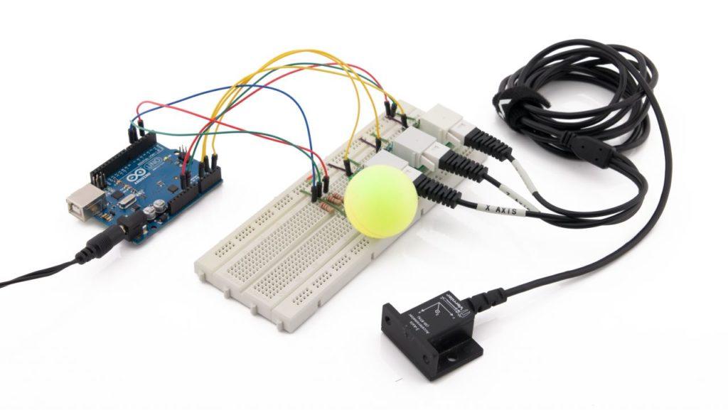
This is a simple, but visually interesting, project. Use a Vernier 3-Axis Accelerometer connected to three BTA sockets. Continuously monitor the voltage of each of these three accelerometers and use the readings to control the brightness of the red, green, and blue LED. Note that the signal from an accelerometer changes depending on how it is oriented. The highest voltage is produced when the arrow on the accelerometer points up and the lowest when the accelerometer arrow points down. With this sketch running, the color of the RGB LED will change to almost any color you want, depending on how you hold the Accelerometer.
The sketch to use for this project is called Vernier3DAAutoscale. It is written with a 15-second calibration period when it first runs. Start the program, the LED will flash once. For the first 15 seconds, gently rotate the 3D Accelerometer so that all three arrows on it point in every direction. The program will take readings which will be used to “calibrate” the brightness ranges of the three LEDs. After the 10 second period, the LED will flash again and from then on, the color will change with accelerometer orientation. If you choose not to calibrate the program simply leave the unit alone through this initial 15 seconds and it will use default values we have provided.
Note that this project requires a RGB LED connected to three digital output lines. It also is the only time we use a third BTA socket. You can still use this sketch with just two BTA sockets. Plug in the X and Y acceleration connectors, and experiment
/*
Vernier3DA (v 2017.08)
This project assumes that you have a Vernier 3D Accelerometer connected to
three BTA connectors. It also assumes that you have an RGB LED connected to
PWM outputs 3, 5, and 6.

Plug x into the first BTA (A0), y into the second BTA (A2), and z into
the third BTA (A4).
The brightness of the red LED is controlled by the x axis acceleration.
The brightness of the green LED is controlled by the y axis acceleration.
The brightness of the blue LED is controlled by the z axis acceleration.

During the first 15 seconds of this program you should rotate the
accelerometer through all 3 axes. This will calibrate the signal for
you specific accelerometer. If you do not rotate the sensor it will
default to set values. All LEDs will flash for 1 second at the beginning
and end of this "calibration".
After calibration, each color should progress through a range of "off" to
full power based on the orientation of the accelerometer. Sitting flat on a
surface (z-axis up) is blue, flat on its side (y-axis up) is green, and cord
facing down is red.
Note that either individual LEDs or a RGB LED may be used.

See www.vernier.com/arduino for more information.
*/
const int RedPin = 3;
const int GreenPin = 5;
const int BluePin = 6;

const int sensorPinRed = A0;
const int sensorPinGreen = A2;
const int sensorPinBlue = A4;

int var = 1;
int minReadingRed = 450; // Default value if no calibration
int maxReadingRed = 600; // Default value if no calibration
int minReadingGreen = 450;
int maxReadingGreen = 600;
int minReadingBlue = 500;
int maxReadingBlue = 830;

int analogValueR = 0;
int analogValueG = 0;
int analogValueB = 0;
int time;
int analogOut;

void setup()
{
  Serial.begin(9600);

}
void loop()
{
  while (time < 1000){ // LEDs to flash at start of calibration
      time = millis();
  analogWrite(RedPin, 255);
  analogWrite(GreenPin, 255);
  analogWrite(BluePin, 255);
  delay (1000);
  analogWrite(RedPin, 0);
  analogWrite(GreenPin, 0);
  analogWrite(BluePin, 0);
  delay (10);}
    while (time>1000 && time < 16000){
        time = millis();
    // Time to calibrate each sensor to it's particular range of values.
    //Red
    analogValueR = analogRead(sensorPinRed);
    maxReadingRed = max(analogValueR, maxReadingRed);
    minReadingRed = min(analogValueR, minReadingRed);// This is the absolute min. We'll adjust this up
    //Green
    analogValueG = analogRead(sensorPinGreen);
    maxReadingGreen = max(analogValueG, maxReadingGreen);
    minReadingGreen = min(analogValueG, minReadingGreen);// This is the absolute min. We'll adjust this up
    //Blue
    analogValueB = analogRead(sensorPinBlue);
    maxReadingBlue = max(analogValueB, maxReadingBlue);
    minReadingBlue = min(analogValueB, minReadingBlue);// This is the absolute min. We'll adjust this up
    }
  while(time > 16000 && time < 17000){  // LEDs to flash at finish of calibration
      time = millis();
    Serial.print(minReadingRed);
    Serial.print("/t");
    Serial.println(maxReadingRed);
  analogWrite(RedPin, 255);
  analogWrite(GreenPin, 255);
  analogWrite(BluePin, 255);
  delay (1000);
  analogWrite(RedPin, 0);
  analogWrite(GreenPin, 0);
  analogWrite(BluePin, 0);}

  while (var == 1){
  minReadingRed = minReadingRed+0.25*(maxReadingRed - minReadingRed); // Adjusts minimum value (experiment with factor)
  minReadingGreen = minReadingGreen+0.25*(maxReadingGreen - minReadingGreen);
  minReadingBlue = minReadingBlue+0.25*(maxReadingBlue - minReadingBlue);

  Serial.println();//prints range of each axis
  Serial.print("minReadingRed = " );
  Serial.print(minReadingRed, DEC);
  Serial.print("     maxReadingRed = " );
  Serial.println(maxReadingRed, DEC);
  Serial.print("minReadingGreen = " );
  Serial.print(minReadingGreen, DEC);
  Serial.print("     maxReadingGreen = " );
  Serial.println(maxReadingGreen, DEC);
  Serial.print("minReadingBlue = " );
  Serial.print(minReadingBlue, DEC);
  Serial.print("     maxReadingBlue = " );
  Serial.println(maxReadingBlue, DEC);
  var = 2;
  }
  // Below is scrolling printout

  //Red
  analogValueR = analogRead(sensorPinRed);
  analogValueR = constrain(analogValueR, minReadingRed, maxReadingRed);
  Serial.print("analogValue Red = " );
  Serial.println(analogValueR);
  analogOut = map(analogValueR, minReadingRed, maxReadingRed, 0, 255);
  analogOut = constrain(analogOut, 0, 255);
  Serial.print(" scaled to " );
  Serial.println(analogOut, DEC);
  analogWrite(RedPin, analogOut);

 //Green
  analogValueG = analogRead(sensorPinGreen);
  analogValueG = constrain(analogValueG, minReadingGreen, maxReadingGreen);
  Serial.print("  Green = " );
  Serial.println(analogValueG);
  analogOut = map(analogValueG, minReadingGreen, maxReadingGreen, 0, 255);
  analogOut = constrain(analogOut, 0, 255);
  Serial.print(" scaled to " );
  Serial.println(analogOut, DEC);
  analogWrite(GreenPin, analogOut);

 //Blue
  analogValueB = analogRead(sensorPinBlue);
  analogValueB = constrain(analogValueB, minReadingBlue, maxReadingBlue);
  Serial.print("  Blue = " );
  Serial.println(analogValueB);
  analogOut = map(analogValueB, minReadingBlue, maxReadingBlue, 0, 255);
  analogOut = constrain(analogOut, 0, 255);
  Serial.print(" scaled to " );
  Serial.println(analogOut, DEC);
  analogWrite(BluePin, analogOut);

  delay (500);
}