Shop
- Engineering
- Arduino
- Using Vernier Sensors with Arduino Guide
- Using Vernier Digital (BTD) Sensors with Arduino
Using Vernier Digital (BTD) Sensors with Arduino®
When using a digital sensor with Arduino, you should connect it to the Digital 1 port on the Vernier Arduino Interface Shield or a Digital Protoboard Adapter wired as explained in the Connecting Vernier Sensors to the Arduino using a Breadboard section.
The following pages describe the programming parameters and provide sample sketches for the following Vernier digital sensors.
Motion Detector
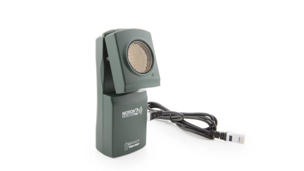
The Motion Detector is probably the most popular of all the Vernier digital sensors. It is used to measure the position of moving objects by sending ultrasound from the gold foil diaphragm and then “listening” for an echo.
The Arduino measures the time from the ultrasound generation to the echo return. The library function, Vernier.readMotionDetector(), uses the speed of sound in room-temperature air and the time for an echo return to calculate the distance to the object in centimeters. Place this function in the loop() portion of your sketch.
distance = Vernier.readMotionDetector();
The sample sketch, VernierLibTutorialMotionDetector, reads the distance to an object and displays the results to the Serial Monitor or Serial Plotter. It assumes you have plugged a Motion Detector into the Digital 1 port on the Vernier Arduino Interface Shield or a Digital Protoboard Adapter wired to Arduino pins 2, 3, 4, and 5 as explained in the Connecting Vernier Sensors to the Arduino Using a Breadboard section.
/* VernierLibTutorialMotionDetector (v2017)
 * This sketch reads the distance to an object and displays the
 * results to the Serial Monitor or Serial Plotter.
 *
 * Plug the Motion Detector into the Digital 1 port on the
 * Vernier Arduino Interface Shield or into a Digital Protoboard
 * Adapter wired to Arduino pins 2, 3, 4, and 5.
 */

#include "VernierLib.h" //include Vernier functions in this sketch
VernierLib Vernier; //create an instance of the VernierLib library

float distance; //create global variable to store sensor reading

void setup() {
  Serial.begin(9600);
  while (!Serial);
  delay(4000);    //Need time for the Serial Monitor to become available
}

void loop() {
  distance = Vernier.readMotionDetector(); //read one data value
  Serial.print(distance); //display data value
  Serial.println(" cm"); //print units
  delay(100); //wait a tenth of a second
}
Photogate
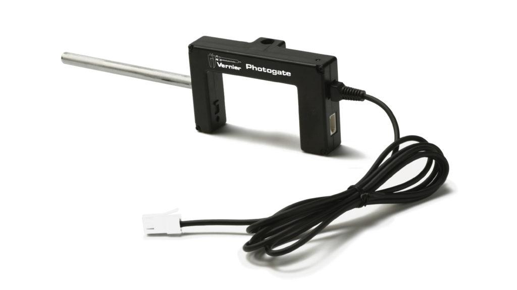
Vernier Photogates provide a way to determine when an object passes a location. They are most often used to study free fall, collisions, speed of rolling objects, and period of a pendulum. You can also use them with the Arduino to trigger an action when the Photogate is blocked.
Plug the Photogate into the Digital 1 port on the Vernier Arduino Interface Shield or a Digital Protoboard Adapter wired to Arduino pins 2, 3, 4, and 5 as explained in the Connecting Vernier Sensors to the Arduino Using a Breadboard section.
The VernierLib library does not support the Photogate, but the sample sketch, VernierTutorialPhotogate, illustrates how to read the status of the photogate, do timing, and display it on the Serial Monitor. This sketch will also turn on an LED (digital line D13) when the photogate is blocked.
You can also use Vernier Photogates with the sketch, VernierTutorialDropCount. This sketch counts the number of times an object passes through the photogate over a period of ten seconds.
/* VernierTutorialPhotogate (v2018)
 * This sketch will send a status message to the Serial
 * Monitor on whether the Photogate is blocked or unblocked.
 * It lists the time that the photogate is blocked in microseconds since the program started running or
 * since the last time the counter overflowed.
 * It will also turn on the LED (pin D13) when the
 * photogate is blocked.
 *
 * Plug the Photogate into the Digital 1 port on the
 * Vernier Arduino Interface Shield or into a Digital Protoboard
 * Adapter wired to Arduino pins 2, 3, 4, and 5.
 */

int photogatePin = 2; //create global variable for pin assignment to sensor
int LEDpin = 13; //create global variable for pin assignment to LED
int photogateStatus; //create global variable for photogate status: LOW=blocked, HIGH=unblocked
int oldStatus = HIGH;
unsigned long timeus = 0; //Time in us

void setup()
  {
    Serial.begin(9600);
    while (!Serial);
    delay(4000);   //Need time for the Serial Monitor to become available
    pinMode(LEDpin, OUTPUT);
    Serial.println("Vernier Format 2");
    Serial.println("Photogate blocked times taken using Ardunio");
    Serial.print("Time");
    Serial.print("us");
  };// end of setup

void loop ()
{
  photogateStatus = digitalRead(photogatePin);//low when blocked
   if (photogateStatus == LOW)
   {
    digitalWrite(LEDpin, HIGH);// turn on LED
        if (oldStatus == HIGH)
          {
          timeus = micros();
          Serial.println(timeus);
           }
   }
   else digitalWrite(LEDpin, LOW);// turn off LED
   oldStatus = photogateStatus;
 } ;// end of loop
Radiation Monitor
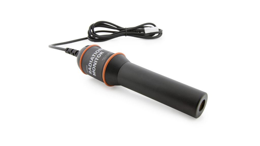
The Vernier Radiation Monitors detects alpha, beta, gamma, and X-ray radiation. Applications include nuclear counting statistics, shielding, and decay rate measurements. The Radiation Monitor produces a signal that can be detected on the Arduino digital lines.
The Radiation Monitor should be connected to the Digital 1 port on the Vernier Arduino Interface Shield or a Digital Protoboard Adapter wired to Arduino pins 2, 3, 4, and 5 as explained in the Connecting Vernier Sensors to the Arduino Using a Breadboard section.
The VernierLib library does not support the Radiation Monitor, but the sample sketch, VernierTutorialRadiation, monitors the sensor and counts the number of radiation events that occur every second. It then reports the number of radiation events on the Serial Monitor.
/* VernierTutorialRadiation (v2017)
 * This sketch monitors a Vernier Radiation Sensor and
 * counts the number of radiation events that occur every
 * second.
 *
 * Plug the Radiation Sensor into the Digital 1 port on the
 * Vernier Arduino Interface Shield or into a Digital Protoboard
 * Adapter wired to Arduino pins 2, 3, 4, and 5.
 */

int sensorPin = 2; //create global variable for pin assignment to sensor
unsigned long timeStart; //create global variable for start time

void setup() {
  Serial.begin(9600);
  while (!Serial);
  delay(4000);   //Need time for the Serial Monitor to become available
}

void loop ()
{
  int radCount = 0; //initialize local variable for number of radiation events

  timeStart = millis(); //set start time to current time
  while ((millis()-timeStart) <= 1000) //do while current time minus start time is less than 1 second
  {
    if (digitalRead(sensorPin)==HIGH) //check if radiation event detected
    {
      radCount ++; //increment number of radiation events
     }
  }
Serial.println(radCount); //print total number of radiation events
}
Drop Counter
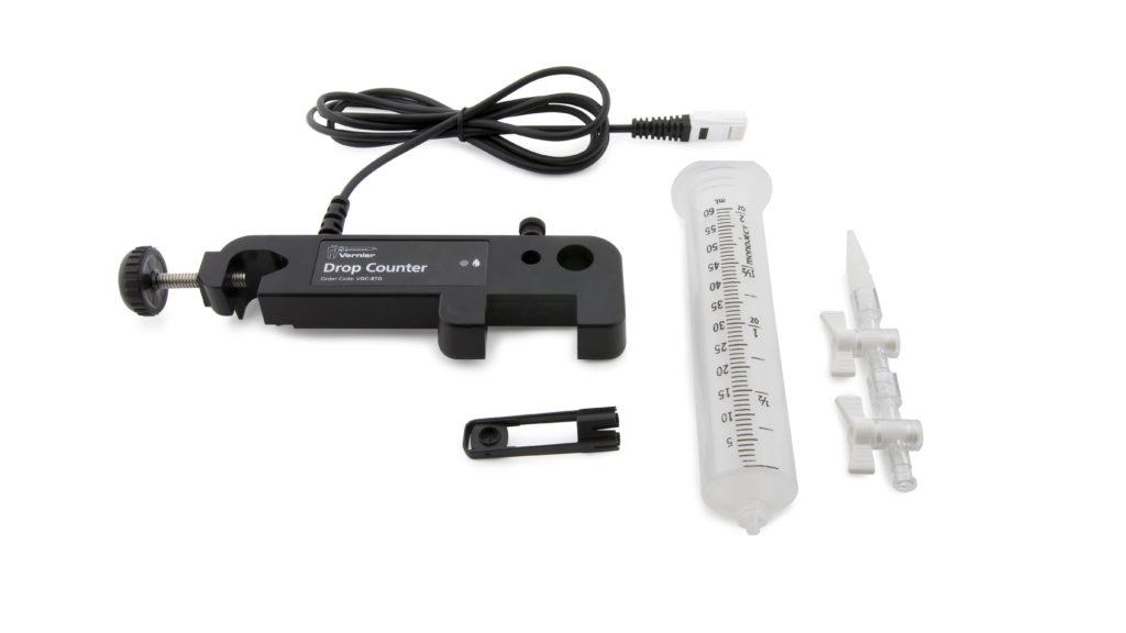
The Vernier Drop Counter records the number of drops that fall from a reagent reservoir. It is often used to perform accurate, automatic titrations. The Drop Counter produces a signal that can be detected on the Arduino digital lines.
The Drop Counter should be connected to the Digital 1 port on the Vernier Arduino Interface Shield or a Digital Protoboard Adapter wired to Arduino pins 2, 3, 4, and 5 as explained in the Connecting Vernier Sensors to the Arduino section.
The VernierLib library does not support the Drop Counter, but the sample sketch, VernierTutorialDropCount, monitors the sensor and counts drop events over a period of ten seconds. It then reports the number of drops on the Serial Monitor. Note the VernierTutorialDropCount sketch can also be used with a Vernier Photogate to count the number of times the photogate beam is blocked during a period of time.
/* VernierTutorialDropCount (v2017)
 * This sketch counts the number of drops that fall through
 * a Vernier Drop Counter or Photogate during a 10 second
 * time period. The number of counts that occured during the 10 s
 * period are printed to the Serial Monitor.
 *
 * Plug the Drop Counter or Photogate into the Digital 1 port
 * on the Vernier Arduino Interface Shield or into a Digital
 * Protoboard Adapter wired to Arduino pins 2, 3, 4, and 5.
 */

int sensorPin = 2; //create global variable for pin assignment to sensor
unsigned long timeStart; //create global variable for start time

void setup() {
  Serial.begin(9600);
  while (!Serial);
  delay(4000);    //Need time for the Serial Monitor to become available
}

void loop () {
  int dropCount = 0; //initialize local variable for number of drops

  timeStart = millis(); //set start time to current time
  while ((millis()-timeStart) <= 10000) //do while current time minus start time is less than 10 seconds
  {
    if (digitalRead(sensorPin)==LOW) //check if drop is blocking sensor
    {
      dropCount ++; //increment number of drops
      while(digitalRead(sensorPin)==LOW); //pause until drop passes through, then continue
     }
  }
Serial.println(dropCount); //print total number of drops
}
Rotary Motion Sensor
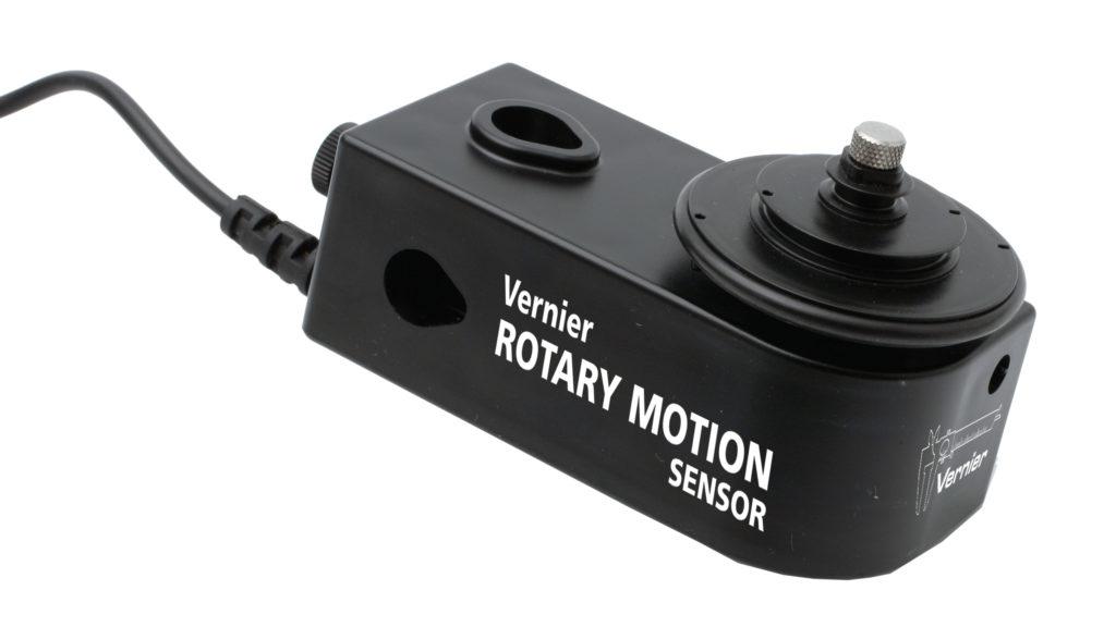
The Vernier Rotary Motion Sensor is a bidirectional angle sensor designed to measure rotational or linear position. It is commonly used to study rotational dynamics, angular momentum, and the period of a pendulum. It produces a pulse on one digital line when it rotates one direction and on another line when it rotates in the other direction. To keep track of the motion of the Rotary Motion Sensor, you can simply tally pulses in each direction.
The Rotary Motion Sensor should be connected to the Digital 1 port on the Vernier Arduino Interface Shield or a Digital Protoboard Adapter wired to Arduino pins 2, 3, 4, and 5 as explained in the Connecting Vernier Sensors to the Arduino section. The VernierLib library does not support the Rotary Motion Sensor, but the sample sketch, VernierTutorialRotaryMotion, tallies the motions in both directions and reports the result every half second.
The pulses that the Rotary Motion Sensor generates are very short. To detect and count them accurately, you need to use “interrupt lines.” Using an interrupt frees the microcontroller to do other tasks while not missing an input from the rotary encoder. (For more information on Arduino interrupts see: http://arduino.cc/en/Reference/AttachInterrupt)
It is useful to know that the Vernier Rotary Motion Sensor can take data in either of two modes. In Normal resolution mode, it measures an angle to the nearest degree. In High-Resolution mode, the Rotary Motion Sensor measures an angle to one quarter of a degree. The VernierTutorialRotaryMotion sketch defaults to Normal resolution, but you can switch to High-Resolution by changing the variable highResOn to True.
/* VernierTutorialRotaryMotion (v2017)
 * This sketch monitors a Vernier Rotary Motion Sensor and
 * returns angle readings every half second. The default
 * mode is Normal resolution (1 deg angle changes), but you
 * can switch to High resolution (0.25 deg angle changes).
 *
 * Plug the Rotary Motion Sensor into the Digital 1 port on the
 * Vernier Arduino Interface Shield or into a Digital Protoboard
 * Adapter wired to Arduino pins 2, 3, 4, and 5.
 */

boolean highResOn = false; //create global variable for resolution mode (normal=false, high=true)
float angleChange; //create global variable for angle measurement
const int encoderPinCCW = 2; //create global variable for pin assignment counterclockwise direction
const int encoderPinCW = 3; //create global variable for pin assignment clockwise direction
const int resPin = 5; //create global variable for pin assignment for resolution mode
volatile int encoderPos = 0; //create global variable for position (variables changed within interrupts are volatile)

void setup() {
  Serial.begin(9600);
  while (!Serial);
  delay(4000);   //Need time for the Serial Monitor to become available

  pinMode(encoderPinCCW, INPUT_PULLUP); //setup CCW pin
  pinMode(encoderPinCW, INPUT_PULLUP); //setup CW pin
  pinMode (resPin, OUTPUT); //setup pin for resolution mode
  if(highResOn) angleChange = 0.25; //check if high resolution is true (angle=0.25 deg)
  else angleChange = 1; //set normal resolution angle to 1 deg
  digitalWrite(resPin,highResOn); //initialize resolution mode
  digitalWrite(encoderPinCCW, LOW); //initialize CCW pin status
  digitalWrite(encoderPinCW, HIGH); //initialize CW pin status
  attachInterrupt(digitalPinToInterrupt(encoderPinCCW), doEncoderCCW, RISING); //trigger when pin goes from LOW to HIGH
  attachInterrupt(digitalPinToInterrupt(encoderPinCW), doEncoderCW, FALLING); //trigger when pin goes from HIGH to LOW
 }

void loop() {
  Serial.println(encoderPos*angleChange); //display angle in degrees
  delay(500); //wait half second
}

void doEncoderCCW() { //create function to measure CCW angle change
    encoderPos++; //count UP
}

void doEncoderCW() { //create function to measure CW angle change
    encoderPos--; //count DOWN
}
Arduino® and
are trademarks of Arduino SA.