Build a Temperature Sensor
Experiment #1 from Engineering Projects with NI LabVIEW and Vernier
- Subject
- Engineering
Introduction
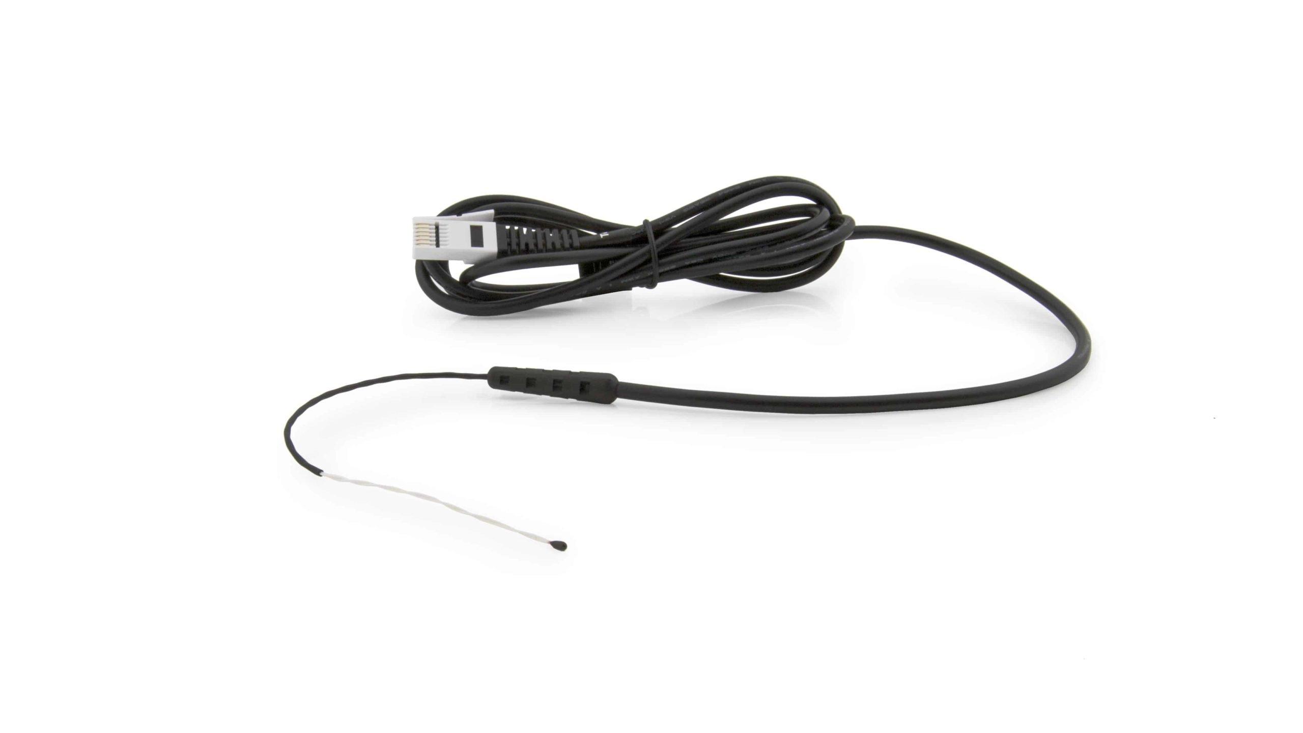
Temperature sensors are often built from electronic components called thermistors. A thermistor is a device whose resistance varies with temperature (the name comes from a combination of the terms “thermal” and “resistor”). Typical thermistors are made from ceramic semiconductors or from platinum wires wrapped around ceramic mandrels or spindles. Thermistors usually have negative temperature coefficients (NTC), meaning the resistance of the thermistor decreases as the temperature increases. Depending on the material and fabrication process, the typical operating range for thermistors is −50°C to 150°C. The small size of most thermistors results in a rapid response to temperature changes making them very useful for control systems requiring quick feedback. They are very rugged and better able to handle mechanical vibration or thermal shock than other temperature sensors. Thermistors have excellent interchangeability due to their low cost, precision, and tolerance over a temperature range. Thermistors are used extensively in many applications, including automobile engines, digital thermostats, rechargeable battery packs, circadian rhythm devices, and fluid-flow measurements.
Objectives
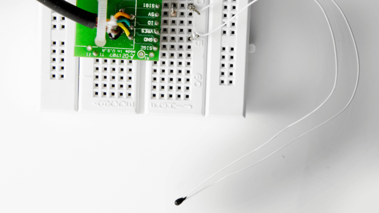
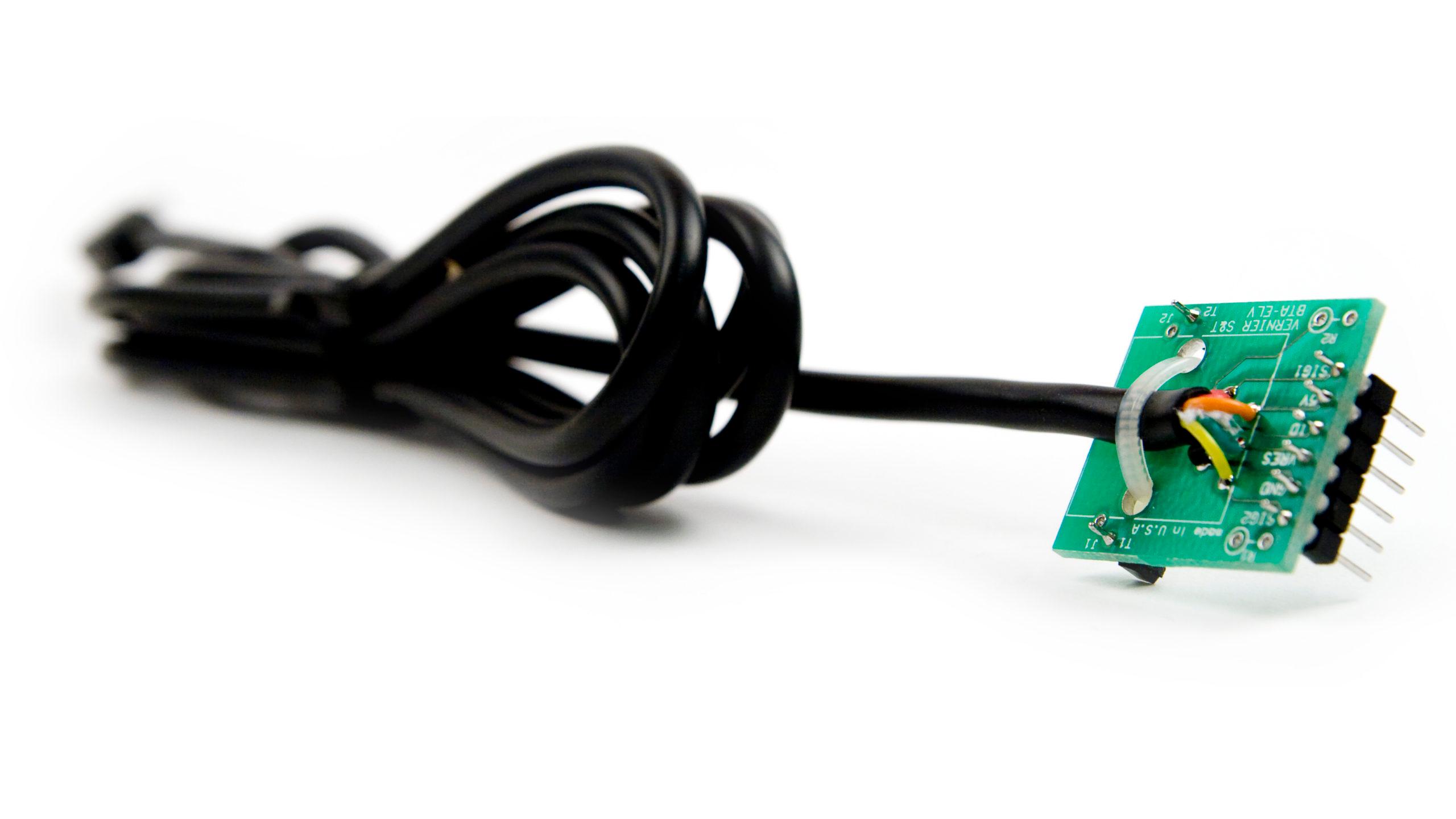
In this Project, you will build and calibrate a temperature sensor. First, you will construct a voltage divider circuit using a thermistor. Then you will write a LabVIEW program to convert the raw voltage reading of the thermistor into Celsius temperature units. Your program should simultaneously collect data from a commercial sensor to verify the readings from your homemade sensor. The temperature values from your homemade sensor and the commercial sensor, as well as the thermistor voltage readings, should be displayed on the front panel.
Sensors and Equipment
This experiment features the following sensors and equipment. Additional equipment may be required.
Ready to Experiment?
Ask an Expert
Get answers to your questions about how to teach this experiment with our support team.
- Call toll-free: 888-837-6437
- Chat with Us
- Email support@vernier.com
Purchase the Lab Book
This experiment is #1 of Engineering Projects with NI LabVIEW and Vernier. The experiment in the book includes student instructions as well as instructor information for set up, helpful hints, and sample graphs and data.