Go Direct® Structures & Materials Tester User Manual
Order Code: GDX-VSMT
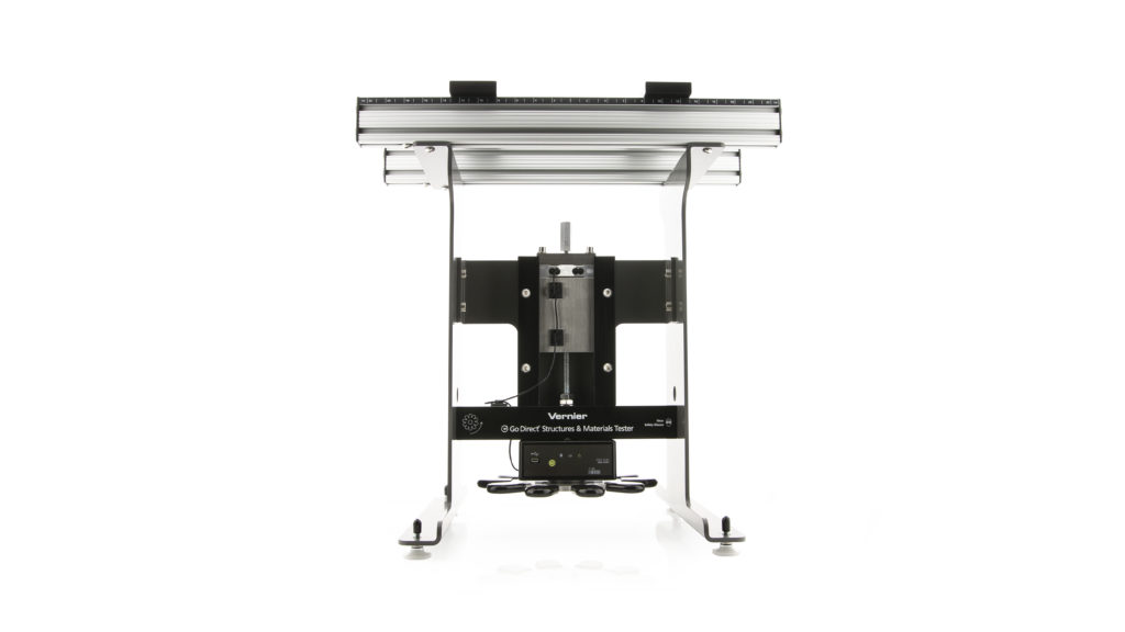
Test bridges, structures, and beams as part of an engineering design activity with Go Direct Structures & Materials Tester. Use the Structures & Materials Tester, along with the engineering design process, to design, build, and test structures, conduct bridge competitions, and investigate and analyze beam designs and properties of materials.
The Structures & Materials Tester is equipped with a force sensor (rated to 1000 N) and an encoder to measure displacement (1 µm resolution). Using both sensors, you can record maximum loads, as well as load versus displacement characteristics, so students can evaluate deflection, stress, and strain.
The crossbars of the Tester are designed to easily slide and secure into position. With rulers located on the Tester, you can accurately position the support beams for center or off-center loading.
The Tester is equipped with a well-outfitted VSMT Tackle Kit. The Kit provides a variety of means to quickly and easily connect the load cell to materials, beams, and structures for testing. The VSMT Tackle Kit is also sold as an accessory kit (order code VSMT-TK). A second Kit may be useful in cases where large numbers of structures are being tested in a short period of time, such as during bridge competitions.
Note: Vernier products are designed for educational use. Our products are not designed nor are they recommended for any industrial, medical, or commercial process such as life support, patient diagnosis, control of a manufacturing process, or industrial testing of any kind.
What's Included
- The testing device with force and displacement sensors
- Micro USB Cable
- Allen wrench
- A VSMT Tackle Kit with hardware to connect bridges, structures, and materials to the tester. This includes
- 50 × 50 mm × 6 mm aluminum load plate
- 50 × 80 mm × 6 mm aluminum load plate
- 12-inch threaded rod
- 8-inch threaded rod
- 6.5 inches of chain
- Small U-bolt
- Large U-bolt
- Eyebolts (2)
- Coupling nut
- Quick links (2)
Compatible Software
Choose a platform below to see its compatibility requirements.LabQuest
Interface LabQuest App LabQuest 3 Full support LabQuest 2 Full support 1 LabQuest Incompatible Compatibility Notes
Computers
Software Interface Graphical Analysis Graphical Analysis (Web App) No interface required Full support Full support LabQuest 3 Full support 1 Incompatible LabQuest 2 Full support 1 2 Incompatible Compatibility Notes
Chromebook
Software Interface Graphical Analysis (Web App) No interface required Full support iOS
Software Interface Graphical Analysis Graphical Analysis GW No interface required Full support Incompatible LabQuest 3 Full support Full support 1 LabQuest 2 Full support 2 Full support 1 2 Compatibility Notes
Android
Software Interface Graphical Analysis Graphical Analysis GW No interface required Full support Incompatible LabQuest 3 Full support Full support 1 LabQuest 2 Full support 2 Full support 1 2 Compatibility Notes
Python
Software Interface Python No interface required Full support Javascript
Software Interface Javascript No interface required Full support LabVIEW
Software Interface NI LabVIEW No interface required Full support
Assembly
Refer to the Go Direct Structures & Materials Tester Assembly Instructions that are shipped with the product. These are also available online at www.vernier.com/gdx-vsmt-assembly
Quick Start: Vernier Graphical Analysis® and Bluetooth®
- Charge your sensor for at least 8 hours before first use.
- Turn on your sensor. The LED will blink red.
- Launch Graphical Analysis, then click Sensor Data Collection.
- Select your sensor from the list. The sensor ID is located on the sensor label near the bar code. Note: If you don’t see a list of available sensors, click WIRELESS. After selecting your sensor, click Pair.
- The active channel is listed in the Connected Devices Sensor Channels list. To change channels, select the check box next to the Sensor Channel(s) you would like to activate.
- Click DONE. You are now ready to collect data.
Using other Vernier data-collection apps or want to connect via USB?
Visit www.vernier.com/start-go-direct
Note: This sensor also works with LabQuest 2 and LabQuest 3; it does not work with the original LabQuest.
Charging the Structures & Materials Tester Battery
Connect the Go Direct Structures & Materials Tester to the included Micro USB Cable and any USB device for eight hours.
You can also charge Go Direct Structures & Materials Tester using our Go Direct Charge Station, sold separately (order code: GDX-CRG).
| Charging |
Orange LED next to battery icon is solid while sensor is charging. |
| Fully charged |
Green LED next to battery icon solid when sensor is fully charged. |
Connecting the Sensor
See the following link for up-to-date connection information:
www.vernier.com/start/gdx-vsmt
Connecting via Bluetooth
| Ready to connect | Red LED next to Bluetooth icon flashes when sensor is awake and ready to connect. |
| Connected | Green LED next to Bluetooth icon flashes when sensor is connected via Bluetooth. |
Connecting via USB
| Connected and charging | Orange LED next to battery icon is solid when sensor is connected to Graphical Analysis via USB and the unit is charging. LED next to Bluetooth is off. |
| Connected, fully charged | Green LED next to battery icon is solid when sensor is connect to Graphical Analysis via USB and fully charged. LED next to Bluetooth icon is off. |
| Charging via USB, connected via Bluetooth |
Orange LED next to battery icon is solid when sensor is connected to charger via USB and the unit is charging. Green LED next to Bluetooth icon flashes when sensor is connected via Bluetooth. |
Identifying the Sensor
You can make the Bluetooth LED flash red and green by clicking Identify in Sensor Information. This is useful to distinguish between two identical sensors.
Using the Product
Connecting your structure/material to be tested securely to the device is critical to the safe and proper use of Go Direct Structures & Materials Tester (GDX‑VSMT). The VSMT Tackle Kit comes with a variety of components that are used to secure the structure/material to the Tester cross bars and connect to the GDX-VSMT force sensor. All structures and materials are generally supported by the crossbars that can be adjusted from 0 cm to over 40 cm. The bars can be secured in place by tightening the hex head screws.
The primary methods of attaching the tackle to the structure/material are to use a U-bolt in combination with quick links (and chain, as needed), or by using a threaded rod and load plate.
Once the structure or beam is secured in place with the appropriate tackle, launch Graphical Analysis 4 and connect the Go Direct Structures & Materials Tester as described in the Quick Start section. Turn the displacement wheel counter clockwise and the force sensor travels down, applying a force to the structure or beam via the tackle. The GDX-VSMT force sensor registers the force while the GDX-VSMT displacement sensor tracks how far the structure has been deflected, bent, or stretched.
Zeroing the Sensors
Zero both of the sensors before any data collection. The VSMT displacement and force sensors should be zeroed with the tackle just in contact with the structure or beam immediately before applying a force.
If a structure is attached to the GDX-VSMT force sensor by means of a rigid connection (e.g., a threaded rod), the tackle is supported by the force sensor. Zero the force sensor with the tackle attached so that the sensor will register only the force actually applied to the structure.
If a structure is attached to the GDX-VSMT force sensor by means of a non-rigid connection (e.g., U-bolt, quick link and chain) then the weight of the tackle is an additional force that is applied to the structure. If necessary for your investigation you can account for the weight of the tackle by adding a new calculated column.
Force Sensor Overload Warning
If the force applied to the force sensor exceeds its rated load of 1,000 N (225 lbs) a red light will appear on the face of the sensor electronics box. This is the indication that no additional force should be applied in order to avoid damaging the sensor.
Specifications
|
Range |
Force 0–1000 N Displacement ~ 0–7 cm |
|
Resolution |
Force 0.1 N Displacement 1 µm |
|
Battery |
650 mAh Li-Poly Rechargeable |
|
Battery life (single full charge) |
~10 hours continuous data collection |
|
Battery life (long term) |
~300 full charge cycles (several years depending on usage) |
Safety
Go Direct Structures & Materials Tester is capable of storing energy as it applies force to structures being tested. When structures fail under stress they can release that energy very quickly. Vernier recommends the use of safety glasses when using the VSMT to protect eyes from flying debris.
It is also important to connect the tackle securely. Threaded parts should be attached so that a sufficient amount of the threaded component is engaged. For example, the threaded rod should extend through the load plate so that its end is at least flush with the upper surface. Quick links should be secured and not left open.
Care and Maintenance
Battery Information
The Go Direct Structures & Materials Tester contains a small lithium-ion battery. The system is designed to consume very little power and not put heavy demands on the battery. Although the battery is warranted for one year, the expected battery life should be several years. Replacement batteries are available from Vernier (order code: GDX-BAT-650).
Storage and Maintenance
To store the Go Direct Structures & Materials Tester for extended periods of time, put the device in sleep mode by holding the button down for at least three seconds. The red LED will stop flashing to show that the unit is in sleep mode. Over several months, the battery will discharge but will not be damaged. After such storage, charge the device for a few hours, and the unit will be ready to go.
Exposing the battery to temperatures over 35°C (95°F) will reduce its lifespan. If possible, store the device in an area that is not exposed to temperature extremes.
Water Resistance
The Go Direct Structures & Materials Tester is not water resistant and should never be immersed in water.
If water gets into the device, immediately power the unit down (press and hold the power button for more than three seconds). Disconnect the sensor and charging cable and remove the battery. Allow the device to dry thoroughly before attempting to use the device again. Do not attempt to dry using an external heat source.
How the Sensors Work
Go Direct Structures & Materials Tester (GDX-VSMT) uses a reflective optical encoder to measure rotation of the wheel which is translated into deflection. The encoder disc is mounted on the threaded rod and has 794 reflective and non-reflective sectors. The encoder produces two pulse output patterns 90º apart in phase. The movement of the threaded rod is determined by counting the pulses. The phase relationship between the output signals determines the direction of rotation.
Go Direct Structures & Materials Tester uses this count to determine the revolutions of the wheel (or fractions, thereof). The GDX-VSMT displacement and force sensors are linked by a threaded rod with a pitch of 16 (16 threads per inch).
The force sensor uses strain gauge technology to measure a change in resistance with a change in force applied to the sensor.
Troubleshooting
For troubleshooting and FAQs, see www.vernier.com/til/4505
Repair Information
If you have followed the troubleshooting steps and are still having trouble with your Go Direct Structures & Materials Tester, contact Vernier Technical Support at support@vernier.com or call 888-837-6437.
Accessories/Replacements
|
Item |
Order Code |
|---|---|
|
VSMT-TK |
|
|
GDX-BAT-650 |
|
|
CB-USB-MICRO |
|
|
CB-USB-C-MICRO |
Go Direct Bridge Competition Software
Go Direct Bridge Competition Software is a free standalone application for Windows® computers used for bridge (or other structure) competitions conducted with Go Direct Structures & Materials Tester. The software provides a visual representation of the force acting on the structure, as well as a comparison to previously tested structures.
Warranty
Warranty information for this product can be found on the Support tab at www.vernier.com/gdx-vsmt/#support
General warranty information can be found at www.vernier.com/warranty
Contact Support
Fill out our online support form or call us toll-free at 1-888-837-6437.