Go Direct® Force Plate User Manual
Order Code: GDX-FP
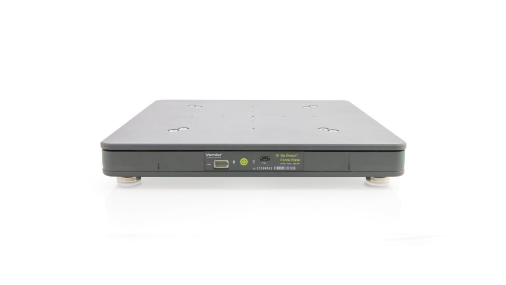
Designed for much higher forces than the Dual-Range Force Sensor, Go Direct Force Plate can measure the forces developed during stepping, jumping, and other human-scale actions. For example, you can perform the following kinds of experiments:
- Observe the change in normal force during an elevator ride.
- Measure the impulse delivered by the floor during a jump.
- Measure the reaction force as a student leans against a wall.
Note: Vernier products are designed for educational use. Our products are not designed nor are they recommended for any industrial, medical, or commercial process such as life support, patient diagnosis, control of a manufacturing process, or industrial testing of any kind.
What's Included
- Go Direct Force Plate
- Pair of handles (1)
- Micro USB Cable
Compatible Software
Choose a platform below to see its compatibility requirements.LabQuest
Interface LabQuest App LabQuest 3 Full support LabQuest 2 Full support 1 LabQuest Incompatible Compatibility Notes
Computers
Software Interface Graphical Analysis Graphical Analysis (Web App) No interface required Full support Full support LabQuest 3 Full support 1 Incompatible LabQuest 2 Full support 1 2 Incompatible Compatibility Notes
Chromebook
Software Interface Graphical Analysis (Web App) No interface required Full support iOS
Software Interface Graphical Analysis Graphical Analysis GW No interface required Full support Incompatible LabQuest 3 Full support 1 2 Full support 1 2 LabQuest 2 Full support 1 2 3 Full support 1 2 3 Compatibility Notes
Android
Software Interface Graphical Analysis Graphical Analysis GW No interface required Full support Incompatible LabQuest 3 Full support 1 2 Full support 1 LabQuest 2 Full support 1 2 3 Full support 1 3 Compatibility Notes
Python
Software Interface Python No interface required Full support Javascript
Software Interface Javascript No interface required Full support 1 Compatibility Notes
LabVIEW
Software Interface NI LabVIEW No interface required Full support
Assembly
Attach feet to the four corners of the bottom of the plate. The feet are not required, but make it easier to lift off of surfaces.
Quick Start: Vernier Graphical Analysis® and Bluetooth®
- Charge your sensor for at least 2 hours before first use.
- Turn on your sensor. The LED will blink red.
- Launch Graphical Analysis, then click Sensor Data Collection.
- Select your sensor from the list. The sensor ID is located on the sensor label near the bar code. Note: If you don’t see a list of available sensors, click WIRELESS. After selecting your sensor, click Pair.
- This is a multi-channel sensor. Click SENSOR CHANNELS and select the channel(s) you want to use.
- Click DONE. You are now ready to collect data.
Using other Vernier data-collection apps or connecting via USB?
Safety
When using the force plate for Hang time and Jump height, students may get aggressive in their efforts. We recommend creating a platform around the force plate to protect against twisted ankles.
Charging the Sensor
Connect Go Direct Force Plate to the included Micro USB Cable and any USB device for two hours.
You can also charge up to eight Go Direct Force Plate Sensors using our Go Direct Charge Station, sold separately (order code: GDX-CRG). An LED on each Go Direct Force Plate indicates charging status.
| Charging |
Orange LED next to battery icon is solid while sensor is charging. |
| Fully charged |
Green LED next to battery icon solid when sensor is fully charged. |
Powering the Sensor
| Turning on the sensor |
Press button once. Red LED indicator next to Bluetooth icon flashes when unit is on. |
| Putting the sensor in sleep mode |
Press and hold button for more than three seconds to put into sleep mode. Red LED indicator stops flashing when sleeping. |
Connecting the Sensor
See the following link for up-to-date connection information:
Connecting via Bluetooth
| Ready to connect | Red LED next to Bluetooth icon flashes when sensor is awake and ready to connect. |
| Connected | Green LED next to Bluetooth icon flashes when sensor is connected via Bluetooth. |
Connecting via USB
| Connected and charging | Orange LED next to battery icon is solid when sensor is connected to Graphical Analysis via USB and the unit is charging. LED next to Bluetooth icon is off. |
| Connected, fully charged | Green LED next to battery icon is solid when sensor is connect to Graphical Analysis via USB and fully charged. LED next to Bluetooth icon is off. |
| Charging via USB, connected via Bluetooth |
Orange LED next to battery icon is solid when sensor is connected to charger via USB and the unit is charging. Green LED next to Bluetooth icon flashes when sensor is connected via Bluetooth. |
Identifying the Sensor
When two or more sensors are connected, the sensors can be identified by tapping or clicking Identify in Sensor Information.
Using the Product
Zeroing the Sensor
In some situations you may want to zero Go Direct Force Plate, because changing the physical orientation of the sensor will change the reading when no force is applied. After you have set up your experiment, use your data-collection software to zero the sensor. Also, in the case of experiments involving large impact forces, you may need to zero the reading again after an impact has taken place.
The Handles
Go Direct Force Plate includes two handles and four screws. You can attach the handles to the back side of the plate using the threaded holes. Do not step on the force plate when the handles are attached.
With handles in place, you can support the unit by hand for pushing on a wall or other large object.
Channels
Go Direct Force Plate has six sensor channels. The channel names are
- Force (N)
- Lateral Force (N)
- Auxiliary Voltage (V)
- X-axis Balance (relative scale)
- Y-axis Balance (relative scale)
- Hang time (s)
- Jump Height (m)
Some notes about the channels:
- Lateral force is designed for use with the Lateral Force Accessory (order code 2D-FP). Use this channel when you have a Lateral Force Accessory connected to the Aux port.
- Auxiliary voltage provides raw voltage from most Vernier analog sensors when connected to the Auxiliary port. Raw voltage data from a sensor can be converted to more typical sensor readings using a sensor’s calibration equation as the expression in a calculated column. The Aux port is only powered when the Auxiliary voltage channel is selected.
- X-axis and Y-axis Balance are designed to be used together with the graph showing X-axis Balance on the X-axis and Y-axis Balance on the Y-axis. We recommend having data plotted as dots vs. connected lines. Set both X-axis and Y-axis ranges to go from –100 to 100. Have a person stand on the force plate, click or tap on one of the Sensor Actions buttons, and click or tap Calibrate. The pattern provides a relative indication of stability while standing on the force plate. Standard deviation from Statistics provides a quantification of that stability measurement.
- Hang time produces the time an individual is in the air, assuming they step on the force plate and then jump and land on the plate.
- Jump Height calculates the height of the jump based on the hang time and acceleration due to gravity.
Calibrating the Sensor
Optional Calibration Procedure
For most experiments, you do not have to calibrate Go Direct Force Plate. A stored calibration is used when the software is started.
If you want to improve the calibration, it is easy to recalibrate following the same procedure used in calibrating most Vernier probes—a two-point calibration. One point is your zero, with no force applied to the sensor. Set the force plate on a level surface. Select the calibration option of the program you are using and remove all force from the force plate. Enter 0 (zero) as the first known intensity. Now apply a known force to the plate. The easiest way to do this is to put an object of known weight centered on the plate. For the best results, take care to accurately center the weight on the force plate. The weight should be at least 25% of the range. Enter the weight of the mass (Note: 1 kg weighs 9.8 N). Do not exceed the sensor's range setting during the calibration.
Consult the instructions or help files appropriate to your software. See also www.vernier.com/til/4011/
Specifications
|
Force range |
–350 to +3500 N |
|
Maximum non-damaging force |
4500 N (1000 lb) compression |
|
Resolution |
1.0 N |
|
Dimensions |
31.5 cm × 31.5 cm × 3.5 cm |
|
Maximum sampling rate |
500 samples per second |
Care and Maintenance
Battery Information
Go Direct Force Plate contains a small lithium-ion battery. The system is designed to consume very little power and not put heavy demands on the battery. Although the battery is warranted for one year, the expected battery life should be several years. Replacement batteries are available from Vernier (order code: GDX-BAT-300).
Storage and Maintenance
To store Go Direct Force Plate for extended periods of time, put the device in sleep mode by holding the button down for at least three seconds. The red LED will stop flashing to show that the unit is in sleep mode. Over several months, the battery will discharge but will not be damaged. After such storage, charge the device for a few hours, and the unit will be ready to go.
Exposing the battery to temperatures over 35°C (95°F) will reduce its lifespan. If possible, store the device in an area that is not exposed to temperature extremes.
Water Resistance
Go Direct Force Plate is not water resistant and should never be immersed in water.
If water gets into the device, immediately power the unit down (press and hold the power button for more than three seconds). Disconnect the sensor and charging cable, and remove the battery. Allow the device to dry thoroughly before attempting to use the device again. Do not attempt to dry using an external heat source.
How the Sensor Works
The Go Direct Force Plate has four load cells located in each of the corners. The signals from these load cells are combined into a single signal to determine the force being applied.
The individual readings are also used with the X-axis balance and Y-axis balance channels. The individual load cell readings are combined to provide a relative stability reading for each axis on a scale between –100 and 100.
Troubleshooting
For troubleshooting and FAQs, see www.vernier.com/til/18853
Repair Information
If you have followed the troubleshooting steps and are still having trouble with your Go Direct Force Plate, contact Vernier Technical Support at support@vernier.com or call 888-837-6437. Support specialists will work with you to determine if the unit needs to be sent in for repair. At that time, a Return Merchandise Authorization (RMA) number will be issued and instructions will be communicated on how to return the unit for repair.
Accessories/Replacements
| Item | Order Code |
|---|---|
|
FP-HAN |
Warranty
Warranty information for this product can be found on the Support tab at www.vernier.com/gdx-fp/#support
General warranty information can be found at www.vernier.com/warranty
Disposal
When disposing of this electronic product, do not treat it as household waste. Its disposal is subject to regulations that vary by country and region. This item should be given to an applicable collection point for the recycling of electrical and electronic equipment. By ensuring that this product is disposed of correctly, you help prevent potential negative consequences on human health or on the environment. The recycling of materials will help to conserve natural resources. For more detailed information about recycling this product, contact your local city office or your disposal service.
Battery recycling information is available at www.call2recycle.org
Do not puncture or expose the battery to excessive heat or flame.
 The symbol, shown here, indicates that this product must not be
disposed of in a standard waste container.
The symbol, shown here, indicates that this product must not be
disposed of in a standard waste container.
Contact Support
Fill out our online support form or call us toll-free at 1-888-837-6437.