Go Direct® Projectile Launcher User Manual
Order Code: GDX-PL
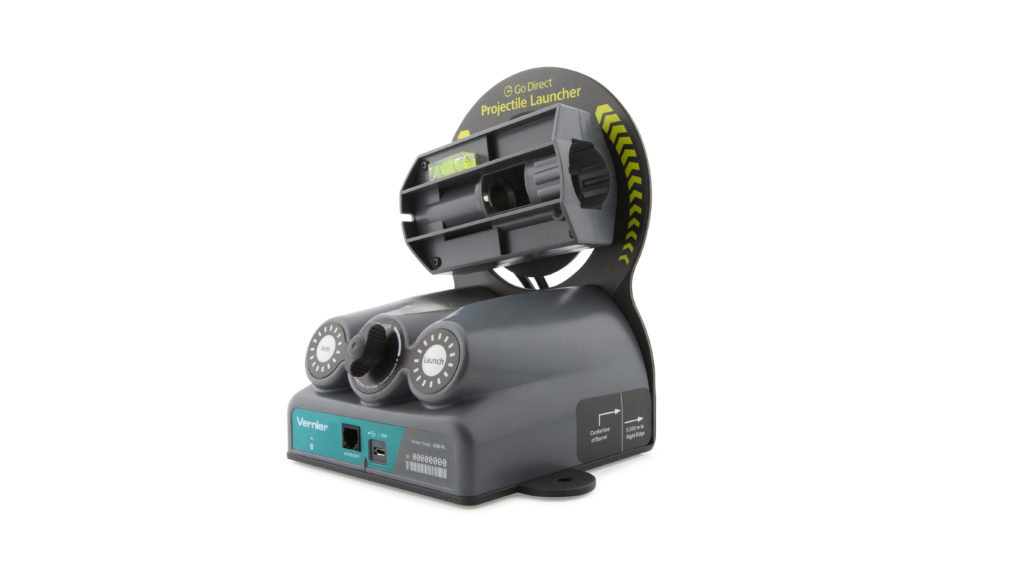
The Go Direct Projectile Launcher allows students to investigate important concepts in two-dimensional kinematics.
Sample experiments include
- Investigate projectile range as a function of launch angle.
- Measure the launch speed of a projectile.
- Predict the ball landing point from the initial speed of a horizontally launched ball.
- Predict the ball landing point from the initial launch speed and angle.
- Attempt to hit a target.
Note: Vernier products are designed for educational use. Our products are not designed nor are they recommended for any industrial, medical, or commercial process such as life support, patient diagnosis, control of a manufacturing process, or industrial testing of any kind.
What's Included
- Go Direct Projectile Launcher
- 6 Steel balls
- Hand pump
- 2 Pairs of safety goggles
- Level
- Roll of waxed marking paper
- Micro USB Cable
Compatible Software
Choose a platform below to see its compatibility requirements.LabQuest
Interface LabQuest App LabQuest 3 Full support LabQuest 2 Full support 1 LabQuest Incompatible Compatibility Notes
Computers
Software Interface Graphical Analysis Graphical Analysis (Web App) No interface required Full support Full support LabQuest 3 Full support 1 Incompatible LabQuest 2 Full support 1 2 Incompatible Compatibility Notes
Chromebook
Software Interface Graphical Analysis (Web App) No interface required Full support iOS
Software Interface Graphical Analysis Graphical Analysis GW No interface required Full support Incompatible LabQuest 3 Full support 1 2 Full support 1 LabQuest 2 Full support 1 2 3 Full support 1 3 Compatibility Notes
Android
Software Interface Graphical Analysis Graphical Analysis GW No interface required Full support Incompatible LabQuest 3 Full support 1 2 Full support 1 LabQuest 2 Full support 1 2 3 Full support 1 3 Compatibility Notes
Python
Software Interface Python No interface required Full support Javascript
Software Interface Javascript No interface required Full support 1 Compatibility Notes
LabVIEW
Software Interface NI LabVIEW No interface required Full support
Quick Start: Vernier Graphical Analysis® and Bluetooth®
- Connect the unit to a USB device such as a USB port on a computer or Chromebook, a USB wall outlet, or a USB power brick
- Launch Graphical Analysis, then click Sensor Data Collection.
- Select your sensor from the list. The sensor ID is located on the sensor label near the bar code. Note: If you don’t see a list of available sensors, click WIRELESS. After selecting your sensor, click Pair.
- Click DONE. You are now ready to collect data.
Note: Be sure to always load the ball into the chamber before starting data collection, as your fingers will pass through the arms of the photogates.
Using other Vernier data-collection apps or want to connect via USB?
Visit www.vernier.com/start-go-direct
Note: This sensor also works with LabQuest 2 and LabQuest 3; it does not work with the original LabQuest.
Powering the Sensor
Connect the unit to a USB device such as a USB port on a computer or Chromebook, a USB wall outlet, or USB power brick. External power is required even if you are using the device with a wireless data connection. When connected to a USB port with adequate power, the unit will automatically wake up.
Connecting the Sensor
See the following link for up-to-date connection information:
Connecting via Bluetooth Wireless Technology
| Ready to connect | Red LED flashes when sensor is powered and ready to connect. |
| Connected | Green LED flashes when sensor is connected via Bluetooth wireless technology. |
Connecting via USB
| Connected via USB, data-collection software is not running | Red LED flashes when sensor is powered and ready to connect. |
| Connected via USB, data-collection software is running | Green LED is solid when connected to the software via USB. |
Identifying the Sensor
Use the Identify feature to flash the LED on the sensor that is connected via Bluetooth wireless technology. In Graphical Analysis, Identify is accessed from Sensor Information. In LabQuest App, Identify is accessed by tapping the sensor meter, then tapping Go Direct.
Using the Product
Follow these steps when using the Go Direct Projectile Launcher when performing basic launch experiments.
- Place the launcher on a flat surface and secure. We recommend placing the launcher on a sturdy table and securing the launcher to the table with table clamps (not included).
- Connect the hand pump to the launcher.
- Connect the sensor following the steps in the Getting Started section of this user manual.
- Loosen the knob on the back of the unit, rotate the launch chamber to the desired launch angle, then secure the knob.
- Set the release pressure by adjusting the range knob. Turn clockwise for higher pressure and higher muzzle velocity and counter-clockwise for lower pressure and lower muzzle velocity.
- Insert one steel ball into the launch chamber. This is most easily done by inserting the ball into the launch chamber with your index finger, guiding the ball into the launch chamber. The ball should seat all the way to the back of the launch chamber.
- Pump the hand pump until the pressure stabilizes. You should hear a small release sound when that pressure is reached. We recommend listening for at least three small release sounds and then waiting for five seconds to ensure the pressure has fully stabilized.
- Start data collection.
- Press and hold the Arm button. While still pressing the Arm button, press the Launch button to launch the steel ball.
- Observe the range of the ball and position the waxed tape along the line of sight for subsequent data collection.
Channels
The Go Direct Projectile Launcher has two measurement channels, both of which are active when the sensor is connected. The channel names are
- Launch Speed
- Launch Angle
Note: The two embedded photogates and the accessory port are logically linked together to provide a single-channel output from these sensors, reported as Gate State. The gate state data is used to determine the launch speed of the projectile.
Calibrating the Sensor
Angle
The Angle sensor channel is factory calibrated before the sensor is shipped. It is possible to apply a single-point calibration offset if the displayed angle is off compared to a known angle (as determined by using a level).
To set the angle calibration offset, complete the following steps:
- Click or tap the angle channel meter to view sensor options.
- Select Calibrate.
- Adjust the launch barrel to the desired position.
- Enter the known angle and click or tap Keep.
- Click or tap Apply to store the calibration offset to the sensor.
To remove the offset and restore the factory calibration, complete the following steps:
- Click or tap the angle channel meter and choose Calibrate.
- Click or tap Reset to Defaults to restore the factory calibration.
Note: The embedded photogates do not require calibration.
Specifications
|
Launch angle |
0–90 degrees |
|
Launch speed |
0–6 m/s |
|
Initial launch height |
146 mm |
|
Maximum launch distance |
2.5 m |
|
Internal photogate interval |
50 mm |
|
Steel ball diameter |
17.46 mm |
|
Steel ball mass |
21.8 g |
|
Maximum pressure (pressurizing chamber) |
100 PSI |
Safety
Two pairs of safety goggles are included for safety. We recommend students and instructors wear the goggles at all times while using this product, including anyone in the vicinity of the projectile launch and landing areas. If needed, additional safety goggles can be purchased from Vernier (see Accessories/Replacement Parts).
The launching system requires simultaneous engagement of the “Arm” and “Launch” buttons to prevent accidental launches. Do not attempt to override or disable this feature.
Other safety considerations
- Do not put your face, hands, or other body parts near the end of the launch chamber while launching.
- Do not aim the launcher at a person or animal.
- Do not attempt to remove the ball from the launch chamber by hand while the chamber is pressurized.
- Only apply pressure to the chamber using the pump provided.
- Important: Do not exceed 100 PSI when pressurizing the chamber.
Care and Maintenance
Storing the launcher
Do not store the launcher while pressurized. Fire the launcher several times before removing power, or use the release button located on the pump, below the pressure gauge, to release residual pressure. Remove the pump from the launcher.
Storing the projectiles
The balls are not stainless steel and can corrode over time when exposed to warm, humid environments. To reduce the likelihood of corrosion, keep the balls sealed in an airtight container such as a zipper-closure bag. In very humid environments, consider including a desiccant packet in with the balls.
If the balls do corrode, they will need to be replaced. Do not use any kind of oil on the balls in an attempt to remove the corrosion, as oil will damage the launcher.
Cleaning the projectiles and launcher
Over time, the projectiles (balls) may transfer some dirt to the inner surface of the launch chamber. The design of the launcher depends on a close fit between the ball and the launch chamber, so any additional material will cause friction and launch irregularities.
Occasional cleaning of the projectiles with a clean rag and a commercial solvent such as Goo Gone® or Goof Off® will help keep dirt out of the launch chamber. Isopropyl alcohol is not recommended for this purpose since it will not remove wax, a common source of the dirt.
If dirt does get into the launch chamber, use compressed air to remove any loose debris from the chamber. If necessary, wipe the inside of the launch chamber with a clean rag and solvent as noted above. If the solvent does not remove enough material, wipe the inside of the launch chamber near the lip with 1500 grit sandpaper. It is important to use very fine sand paper; if a coarser grit is used, the inner dimension of the launch chamber may change too much, damaging the launcher.
Water Resistance
Go Direct Projectile Launcher is not water resistant and should never be immersed in water or used in wet environments.
If water gets into the device, immediately disconnect the USB cable from the unit. Allow the device to dry thoroughly before attempting to use the device again. Do not attempt to dry using an external heat source.
How the Sensor Works
The Go Direct Projectile Launcher is used to investigate important concepts in two-dimensional kinematics. A steel ball placed in the launch chamber can be projected with different launch speeds and at different launch angles. A unique pneumatic launching system provides excellent repeatability at angles between 0 and 70 degrees and up to a distance of 2.5 m. Note: As launch angle increases above 70 degrees, the trajectory may deviate from the expected direction of parallel to the vertical plane of the back of the launcher.
The included hand pump is designed for generating the necessary pressure for the pneumatic launching system. The Range turn-knob controls the maximum pressure of the chamber, allowing for different projectile ranges given a constant launch angle. The pump includes a pressure gauge in order to return to an approximate launch speed used earlier. Note that a constant chamber pressure does not guarantee a constant launch speed at different launch angles.
Internal accelerometers are used to determine the angle of the launch chamber with respect to gravity. An angle of 0° indicates the launch chamber is horizontal, an angle of 90° indicates the launch chamber is vertical. (Negative launch angles should be avoided as the ball will not remain seated in the launcher during a launch.) Launch angle is reported by the software.
The launching system requires simultaneous engagement of the “Arm” and “Launch” buttons to initiate a launch. This allows the ball to be launched quickly and easily, while ensuring students’ safety. For more details on the launch procedure, see Using the Product.
Two photogates positioned within the launch chamber allow for precise determination of the ball’s launch speed using Vernier’s software applications. To do this, the software records the time when the ball initially blocks each gate then calculates the difference, known as the pulse time. The launch speed of the ball is then determined from the ratio of the separation distance of the photogates and the pulse time. Alternatively, the software can be configured to record the duration the first gate is blocked, known as the gate time. With this configuration, the average speed of the ball is determined from the ratio of the ball’s diameter (0.0174625 m or 11/16 in) and the gate time.
When using the optional Time of Flight Pad accessory, the time between the initial blocking of the first gate and the projectile striking the Time of Flight Pad is used to determine time of flight. Note: The Time of Flight Pad connects to the Go Direct Projectile Launcher accessory port.
Sample Experiments
There are a variety of experiments that can be performed with this Projectile Launcher. Below you will find several detailed examples. You might want to try them out to learn more about the equipment.
Investigate Projectile Range as a Function of Launch Angle
As a preliminary inquiry activity prior to the study of two-dimensional kinematics, have the students measure the launch range as a function of launch angle.
- Follow the basic launch procedure for a launch angle of 5°.
- Launch the ball such that it strikes the tape.
- Increase the angle 5° for the second trial.
- Repeat Step 3 up to a launch angle of 70°.
- Examine the relationship between launch angle and range. Determine which launch angle produces the maximum range. Note any launch angles that appear to have the same range.
Measure the Launch Speed
Most of the experiments involving the projectile launcher require measurement of the initial launch speed.
- Follow the basic launch procedure for a horizontal launch angle (0°), but do not perform the test launch.
- Position an empty box standing vertically about 50 cm in front of the launcher to catch the ball.
- Launch the ball into the box.
- Record the launch speed.
- Collect nine more readings.
- Determine the average launch speed and its standard deviation.
Predict the Landing Point from the Launch Speed
Once the launch speed of the projectile is known, students can use their knowledge of two-dimensional kinematics to predict where the projectile will land. This activity can be especially challenging if the students use the technique noted above of catching the ball in a box shortly after it leaves the launcher. This approach prevents the students from visually estimating where the ball will land.
- Determine the launch speed as described in the section above.
- Move the setup such that the ball will be launched from the end of a table.
- Use kinematics to calculate the landing spot.
- Place one or two pieces of the waxed marking paper at that location.
- Test your predictions.
Extension 1 – Change the launch speed and repeat Steps 1–5 above.
Extension 2 – Collect nine more readings. Calculate the range spread and the lateral spread from your prediction.
Predict the Landing Point from the Launch Speed and Angle
Perform the same steps as in the previous experiment, but this time launch the ball at various angles.
Attempt to Hit a Target
Challenge your students to launch a ball at a particular target and hit the target on their first trial. For example, challenge them to launch the ball horizontally from a tabletop into an empty soup can. Prior to their only trial, allow them to make as many measurements as needed to best determine the launch speed. In measuring the launch speed, do not allow them to actually project it off the table. Rather, specify that the ball be “caught” by an object such as an open box.
Troubleshooting
For troubleshooting and FAQs, see www.vernier.com/til/4196
Repair Information
If you have followed the troubleshooting steps and are still having trouble with your Go Direct Projectile Launcher, contact Vernier Technical Support at support@vernier.com or call 888-837-6437. Support specialists will work with you to determine if the unit needs to be sent in for repair. At that time, a Return Merchandise Authorization (RMA) number will be issued and instructions will be communicated on how to return the unit for repair.
Accessories/Replacements
| Accessory | Order Code |
|---|---|
|
TOF-VPL |
|
|
IOM-VPL |
|
|
PS-VPL |
|
|
CB-USB-C-MICRO |
| Replacement Part | Order Code |
|---|---|
|
CB-USB-MICRO |
|
|
WXT-VPL |
|
|
STB-VPL |
|
|
GGL-VPL |
|
|
PUMP-VPL |
Warranty
Warranty information for this product can be found on the Support tab at www.vernier.com/gdx-pl/#support
General warranty information can be found at www.vernier.com/warranty
Disposal
When disposing of this electronic product, do not treat it as household waste. Its disposal is subject to regulations that vary by country and region. This item should be given to an applicable collection point for the recycling of electrical and electronic equipment. By ensuring that this product is disposed of correctly, you help prevent potential negative consequences on human health or on the environment. The recycling of materials will help to conserve natural resources. For more detailed information about recycling this product, contact your local city office or your disposal service.
 The symbol, shown here, indicates that this product must not be disposed of in a standard waste container.
Contact Support
Fill out our online support form or call us toll-free at 1-888-837-6437.