Shop
- Engineering
- Arduino
- Using Vernier Sensors with Arduino Guide
- Using the Vernier Digital Control Unit (DCU) with Arduino
Using the Vernier Digital Control Unit (DCU) with Arduino
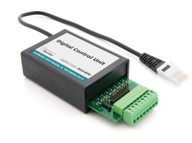
The Vernier Digital Control Unit (DCU) makes it easy to control DC electrical devices, such as LEDs, buzzers, and lamps. DCU projects are a great way to teach concepts in electronics, sensors, feedback and control, automation, and other engineering topics. The VernierLib library contains functions that support control of the DCU.
The DCU should be connected to the Digital 2 port on the Vernier Arduino Interface Shield or a Digital Protoboard Adapter wired to Arduino pins 6, 7, 8, and 9 as explained in the Connecting Vernier Sensors to the Arduino Using a Breadboard section (be sure to use the wiring instructions for a second Digital Protoboard Adapter). An LED on the DCU will provide feedback when it is properly connected. There are two ways to connect your electrical device to the DCU: connect your electrical device to the DCU header pins or screw the electrical device’s wires into the DCU’s screw terminal. Once the electrical device is attached to the DCU, an external power supply, such as the LabQuest Power Supply (not included), may be required to power the device.
Controlling the DCU Output Lines
The DCU contains solid-state relays and other electronic components that allow you to control six DC output lines using only four Arduino digital lines. Each of these lines can drive up to 600 mA of current. The total current from the DCU should not exceed 1000 mA. You control the DCU in the loop() portion of your sketch with the VernierLib function:
Vernier.DCU(DCUSetting);
where DCUSetting can be any integer from 0 to 15 representing one of 16 on/off states.
| DCU LINE | ||||||
|---|---|---|---|---|---|---|
| DCUSETTING | D1 | D2 | D3 | D4 | D5 | D6 |
| 0 | off | off | off | off | off | off |
| 1 | on | off | off | off | off | off |
| 2 | off | on | off | off | off | off |
| 3 | on | on | off | off | off | off |
| 4 | off | off | on | off | off | off |
| 5 | on | off | on | off | off | off |
| 6 | off | on | on | off | off | off |
| 7 | on | on | on | off | off | off |
| 8 | off | off | off | on | off | off |
| 9 | on | off | off | on | off | off |
| 10 | off | on | off | on | off | off |
| 11 | on | on | off | on | off | off |
| 12 | off | off | off | off | off | off |
| 13 | off | off | off | off | on | off |
| 14 | off | off | off | off | off | on |
| 15 | off | off | off | off | on | on |
You can connect up to three DC electrical devices simultaneously using DCU lines D1, D2, and D3. We recommend reserving DCU lines D4, D5, and D6 for servo and stepper motor connections.
The sample sketch, VernierLibTutorialDCUStates, will cycle through each of the 16 possible states for the Vernier DCU once each second. LEDs on the DCU will turn on or off to indicate the status of each digital line. Plug the DCU into the Digital 2 port on the Vernier Arduino Interface Shield or into a Digital Protoboard Adapter wired to Arduino pins 6, 7, 8, and 9 as explained in the Connecting Vernier Sensors to the Arduino Using a Breadboard section.
/* VernierLibDemoDCUStates (v2017)
 * This sketch cycles through each of the 16 possible states
 * for the Vernier DCU once each second. LEDs on the DCU
 * indicate the on/off status of each digital line.
 *
 * Plug the DCU into the Digital 2 port on the Vernier Arduino
 * Interface Shield or into a Digital Protoboard Adapter wired
 * to Arduino pins 6, 7, 8, and 9.
 */

#include "VernierLib.h" //include Vernier functions in this sketch
VernierLib Vernier; //create an instance of the VernierLib library

int DCUSetting; //create global variable for DCU state (0-15)

void setup() {
}

void loop() {
  for (DCUSetting=0; DCUSetting <= 15; DCUSetting++) //cycle through all 16 DCU states
  {
    Vernier.DCU(DCUSetting); //turn on DCU lines for each state
    delay(1000); //wait one second
  }
}
Triggering a Buzzer with Sensor Input
One of the more common activities when building a sensor-based control system is to trigger an indicator when the sensor reading exceeds a threshold value. The sample sketch, VernierLibTutorialDCUThreshold, will turn on a buzzer connected to DCU line D1 when the applied force on a Vernier Dual-Range Force Sensor exceeds 5 newtons. This sketch assumes the buzzer is connected to lines D1 and GND on the DCU. Plug the sensor and DCU into the Analog 1 and Digital 2 ports, respectively, on the Vernier Arduino Interface Shield or into Analog Protoboard Adapter and Digital Protoboard Adapter wired as explained in the Connecting Vernier Sensors to the Arduino Using a Breadboard section.
Note you can substitute other Vernier Analog (BTA) sensors. Simply modify the value of the threshold variable in the sketch. You can also combine up to three electrical devices in your project (we recommend using only the first three digital lines for this type of application).
/* VernierLibTutorialDCUThreshold (v2017)
 * This sketch turns on a DC electrical device connected to DCU
 * line D1 when a Vernier Analog (BTA) sensor exceeds a
 * threshold value.
 *
 * Plug the DCU into the Digital 2 port on the Vernier Arduino
 * Interface Shield or into a Digital Protoboard Adapter wired
 * to Arduino pins 6, 7, 8, and 9. Plug the sensor into the
 * Analog 1 port on the Vernier Arduino Interface Shield or
 * into an Analog Protoboard Adapter wired to Arduino pin A0.
 */

#include "VernierLib.h" //include Vernier functions in this sketch
VernierLib Vernier; //create an instance of the VernierLib library

float sensorReading; //create global variable to store sensor reading
float threshold = 5.0; //set threshold value for a Dual-Range Force Sensor

void setup() {
  Vernier.autoID(); //identify the sensor
}

void loop() {
  sensorReading = Vernier.readSensor(); //get one data point
  if(sensorReading > threshold) //check if threshold exceeded
  {
    Vernier.DCU(1); //turn on DCU line D1
  }
  else
  {
    Vernier.DCU(0); //turn off all DCU lines
  }
  delay(500); //wait half second
}
Triggering a Buzzer with a Button Press
The Vernier Arduino Interface Shield includes a general purpose button connected to digital line 12 on the Arduino. You can use this button to control an action in your project. Before this button will work, however, you need to add this line to the setup portion of your sketch:
pinMode(12,INPUT_PULLUP);
You read the status of the button with this line of code:
int button = digitalRead(12);
The value of button will be LOW when the button is pressed and HIGH when it is not pressed.
The sample sketch, VernierLibTutorialDCUButtonPress, will turn on a buzzer connected to DCU line D1 when the general purpose button on the Vernier Arduino Interface Shield is pressed. The sketch assumes the buzzer is connected to lines D1 and GND on the DCU, and the DCU is plugged into the Digital 2 port on the Vernier Arduino Interface Shield. Note that this sketch will not work with a Digital Protoboard Adapter unless you wire a button to digital line D12 as there is no general purpose button on the adapter.
/* VernierLibTutorialDCUButtonPress (v2017)
 * This sketch turns on a DC electrical device connected to DCU
 * line D1 when the general purpose button on the Vernier
 * Arduino Interface Shield is pressed.
 *
 * Plug the DCU into the Digital 2 port on the Vernier Arduino
 * Interface Shield.
 */

#include "VernierLib.h" //include Vernier functions in this sketch
VernierLib Vernier; //create an instance of the VernierLib library

int button; //create a global variable for button state (LOW=button pressed, HIGH=button not pressed)

void setup() {
  pinMode(12,INPUT_PULLUP); //setup digital line 12 for button state
}

void loop() {
  button = digitalRead(12); //get button state
  if(button = LOW) //check if button pressed down
  {
    Vernier.DCU(1); //turn on DCU line D1
  }
  else //check if button not pressed
  {
    Vernier.DCU(0); //turn off all DCU lines
  }
  delay(500); //wait half second
}
Arduino® and
are trademarks of Arduino SA.