Go Direct® Acceleration Sensor User Manual
Order Code: GDX-ACC
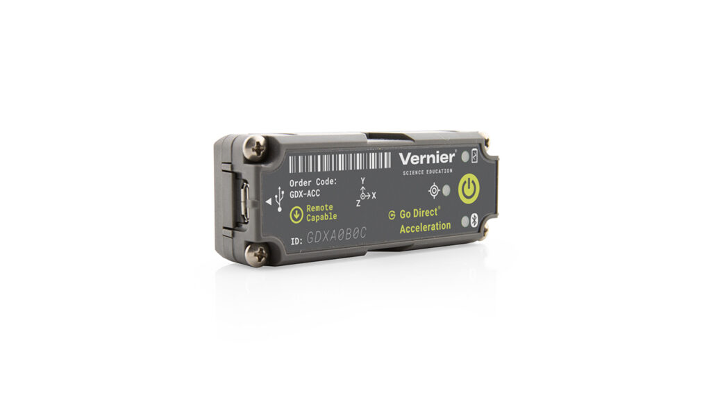
Collect acceleration, rotation, and altitude data in the classroom or in the field. Go Direct Acceleration connects wirelessly via Bluetooth® wireless technology or wired via USB to your device. This 3-axis acceleration sensor has two acceleration ranges plus an altimeter and a 3-axis gyroscope. It also has an angle measurement relative to the x-axis.
- Measure helmet impacts in concussion-related investigations.
- Slip it into your pocket and pirouette or ride a half-pipe.
- Zip-tie this accelerometer to your bicycle or affix it to your lab cart without any dragging cables.
Note: Vernier products are designed for educational use. Our products are not designed nor are they recommended for any industrial, medical, or commercial process such as life support, patient diagnosis, control of a manufacturing process, or industrial testing of any kind.
What's Included
- Go Direct Acceleration
- Micro USB Cable
- Shim plate for cart
- U-bracket for cart
- Cylinder mounting plate
Compatible Software
Choose a platform below to see its compatibility requirements.LabQuest
Interface LabQuest App LabQuest 3 Full support LabQuest 2 Full support 1 LabQuest Incompatible Compatibility Notes
Computers
Software Interface Graphical Analysis Graphical Analysis (Web App) No interface required Full support Full support LabQuest 3 Full support 1 Incompatible LabQuest 2 Full support 1 2 Incompatible Compatibility Notes
Chromebook
Software Interface Graphical Analysis (Web App) No interface required Full support iOS
Software Interface Graphical Analysis Graphical Analysis GW No interface required Full support Full support LabQuest 3 Full support 1 2 Full support 1 2 LabQuest 2 Full support 1 2 3 Full support 1 2 3 Compatibility Notes
Android
Software Interface Graphical Analysis Graphical Analysis GW No interface required Full support Incompatible LabQuest 3 Full support 1 2 Full support 1 LabQuest 2 Full support 1 2 3 Full support 1 3 Compatibility Notes
Python
Software Interface Python No interface required Full support Javascript
Software Interface Javascript No interface required Full support 1 Compatibility Notes
LabVIEW
Software Interface NI LabVIEW No interface required Full support
Quick Start: Vernier Graphical Analysis® and Bluetooth®
- Charge your sensor for at least 2 hours before first use.
- Turn on your sensor. The LED will blink red.
- Launch Graphical Analysis, then click Sensor Data Collection.
- Select your sensor from the list. The sensor ID is located on the sensor label near the bar code. Note: If you don’t see a list of available sensors, click WIRELESS. After selecting your sensor, click Pair.
- This is a multi-channel sensor. Click SENSOR CHANNELS and select the channel(s) you want to use.
- Click DONE. You are now ready to collect data.
Using other Vernier data-collection apps or want to connect via USB?
Visit www.vernier.com/start-go-direct
Note: This sensor also works with LabQuest 2 and LabQuest 3; it does not work with the original LabQuest.
Charging the Sensor
Connect Go Direct Acceleration to the included Micro USB Cable and any USB device for two hours.
You can also charge up to eight Go Direct Acceleration Sensors using our Go Direct Charge Station, sold separately (order code: GDX-CRG). An LED on each Go Direct Acceleration indicates charging status.
| Charging |
Orange LED next to battery icon is solid while sensor is charging. |
| Fully charged |
Green LED next to battery icon solid when sensor is fully charged. |
Powering the Sensor
| Turning on the sensor |
Press button once. Red LED indicator next to Bluetooth icon flashes when unit is on. |
| Putting the sensor in sleep mode |
Press and hold button for more than three seconds to put into sleep mode. Red LED indicator stops flashing when sleeping. |
Connecting the Sensor
See the following link for up-to-date connection information:
Connecting via Bluetooth
| Ready to connect | Red LED next to Bluetooth icon flashes when sensor is awake and ready to connect. |
| Connected | Green LED next to Bluetooth icon flashes when sensor is connected via Bluetooth. |
Connecting via USB
| Connected and charging | Orange LED next to battery icon is solid when sensor is connected to Graphical Analysis via USB and the unit is charging. LED next to Bluetooth icon is off. |
| Connected, fully charged | Green LED next to battery icon is solid when sensor is connect to Graphical Analysis via USB and fully charged. LED next to Bluetooth icon is off. |
| Charging via USB, connected via Bluetooth |
Orange LED next to battery icon is solid when sensor is connected to charger via USB and the unit is charging. Green LED next to Bluetooth icon flashes when sensor is connected via Bluetooth. |
Identifying the Sensor
When two or more sensors are connected, the sensors can be identified by tapping or clicking Identify in Sensor Information.
Using the Product
Connect the sensor following the steps in the Getting Started section of the user manual.
Channels
Go Direct Acceleration has 11 measurement channels:
- X-axis acceleration (m/s2)
- Y-axis acceleration (m/s2)
- Z-axis acceleration (m/s2)
- X-axis acceleration - high (m/s2)
- Y-axis acceleration - high (m/s2)
- Z-axis acceleration - high (m/s2)
- X-axis gyro (rad/s)
- Y-axis gyro (rad/s)
- Z-axis gyro (rad/s)
- Altitude (m)
- Angle (°)
Acceleration
There are six acceleration channels, measured by two different chips, which are located under the 3-axis icon on the sensor label. The icon shows the positive direction for each axis, with the x-direction of acceleration parallel to the length of the sensor and the z-direction straight up through the label. Each direction of acceleration can be measured separately.
If you choose to activate three acceleration channels from one chip at once, you can create a calculated column for the total acceleration magnitude.
Gyroscope
Use the gyroscope channels to measure the rotation rate of the unit. Measured values are positive when the rotation is counter-clockwise relative to the axis directions indicated by the 3-axis icon on the label. For example, when placed label upward on a turntable rotating clockwise, the x- and y- gyroscopes will read close to zero and the z- gyroscope will show a negative reading.
If you choose to activate all three gyroscope channels at once, you can create a calculated column for the total magnitude of angular velocity.
Altitude
The altimeter channel measures altitude with a range of –1800 m to 10,000 m. Zero the altimeter before use to measure relative height above and below your zero level.
Angle
The angle measurement channel uses the ±16 g accelerometer chip and trigonometry to calculate the angle of the x-direction axis relative to horizontal. The green "level" LED,  , will illuminate to indicate 0° (horizontal) or 90° (vertical) inclination, relative to horizontal.
Videos
Calibrating the Sensor
Acceleration
In most cases, calibration is not necessary for this sensor. However, most accelerometers, including this one, sense gravity as well as acceleration. Thus, if you want to measure vertical acceleration separate from gravity, simply place the sensor in its measurement orientation and zero the axis that is pointing vertically upward.
If you plan to use this sensor exclusively for vertical acceleration, it makes sense to calibrate the sensor so that zeroing will not be necessary every time a new experiment is created in the software. Calibration writes an offset value to the sensor, as opposed to setting a zero temporarily for the duration of an experiment. The offset value will then be applied each subsequent time the sensor is used. To calibrate the sensor, click or tap the meter for the axis you wish to offset and choose Calibrate. Orient your sensor as for measurement and enter 0 m/s2 (or whatever offset you choose, for example –19.6 m/s2 if you orient an axis vertically downward instead of upward). Click or tap Keep, then Apply the calibration.
Gyroscope
This sensor is factory calibrated.
Altitude
This sensor is factory calibrated, but you can choose to offset the value based on your physical location using the calibrate option.
Angle
This sensor is factory calibrated.
Specifications
|
Maximum data‑collection rate |
|
|
Acceleration range |
±157 m/s2 |
|
High acceleration range |
±1960 m/s2 (± 200 g) |
|
Gyroscope range |
±35 rad/s (±2000 °/s) |
|
Altitude range |
–1800 m to 10,000 m |
|
Angle range |
±180° |
|
USB specification |
USB 2.0 full speed |
|
Wireless specification |
Bluetooth v4.2 |
|
Maximum wireless range |
30 m (unobstructed) |
|
Dimensions |
68 mm × 27 mm × 17 mm |
|
Least cross section |
28.6 mm |
|
Battery |
300 mA Li-Poly |
|
Battery life (single full charge) |
~24 hours continuous data collection |
|
Battery life (long term) |
Several years depending on usage |
Care and Maintenance
Battery Information
Go Direct Acceleration contains a small lithium-ion battery. The system is designed to consume very little power and not put heavy demands on the battery. Although the battery is warranted for one year, the expected battery life should be several years. Replacement batteries are available from Vernier (order code: GDX-BAT-300).
Storage
To store Go Direct Acceleration for extended periods of time, put the device in sleep mode by holding the button down for at least three seconds. The red LED will stop flashing to show that the unit is in sleep mode. Over several months, the battery will discharge but will not be damaged. After such storage, charge the device for a few hours, and the unit will be ready to go.
Exposing the battery to temperatures over 35°C (95°F) will reduce its lifespan. If possible, store the device in an area that is not exposed to temperature extremes.
Water Resistance
Go Direct Acceleration is not water resistant and should never be immersed in water.
If water gets into the device, immediately power the unit down (press and hold the power button for more than three seconds). Disconnect the sensor and charging cable, and remove the battery. Allow the device to dry thoroughly before attempting to use the device again. Do not attempt to dry using an external heat source.
How the Sensor Works
Accelerometer
The accelerometers are microelectromechanical devices (MEMS devices) each consisting of a cantilever and a test mass. As the mass is accelerated, the cantilever bends, generating a signal proportional to the acceleration. Three orthogonal axes provide three channels of acceleration information for most experiments and an additional three channels of acceleration for high-g situations are also available. Acceleration measurements are used for the angle measurement.
Gyroscope
The gyroscope is a microelectromechanical device that uses a vibrating structure to determine rate of rotation using the Coriolis force on the structure. Three orthogonal axes provide three different channels of rotation information.
Altitude
The altimeter is a temperature-compensated, absolute air pressure sensor that can measure from 260 mBar up to 1260 mBar. We use the following equation to convert to altitude in meters:

assuming that p0, the pressure at sea level, is 1013.25 mBar. The resulting altitude range is from about –1800 m to 10000 m.
The absolute pressure accuracy is ±0.2 mBar which can give you an error of ±1.4 m to ±5 m depending on which end of the scale you are at (–1800 m or 10000 m respectively).
You will often want to study the change in altitude during an experiment. Examples would include roller coaster rides, sky dives, or bungee jumps. In these cases, the absolute altitude above sea level is not as important as relative altitude compared to the ground or to the starting point of data collection. Zero the sensor before collecting data to use relative altitude.
Additional Information about Acceleration
Since the accelerometer is sensitive to both acceleration and the Earth’s gravitational field, interpreting accelerometer measurements is complex. A useful model for understanding accelerometer measurements is a spring-based scale with a reference mass (or object) attached to the scale. If the scale is pointing upward (the usual orientation for such a device) the weight of the mass causes the spring to compress, and you get a non-zero reading. If you were to turn the scale upside down, the spring will be extended, instead of compressed, and we get a reading of the opposite sign. If you turn the scale so it points sideways, and keep it motionless, then the spring will just be at its relaxed length, and the reading will be zero. If you accelerated the scale toward the mass, then the spring would compress. If you accelerate the scale away from the mass the spring would stretch. In each case the scale is reading a value corresponding to the normal force on the mass. This reading can be made relative by dividing out the mass, giving units of N/kg, which is the same as m/s2.
Q: What does an accelerometer measure?
A: It meaures normal force per unit mass, otherwise known as proper acceleration.
Note that it’s not the net force per unit mass (which is acceleration), but it is the normal force per unit mass. This somewhat unusual quantity corresponds with what a rider on a roller coaster feels during the turns. This interpretation is useful even for the scalar total acceleration value, which is 9.8 N/kg for a 3-axis accelerometer at rest, zero for one in free fall, and greater than 9.8 for one rounding a corner.
This normal force interpretation works even for a one-axis accelerometer being accelerated in a horizontal direction. The reading is non-zero as the test mass inside the device has to have a force applied to accelerate it. That’s just a normal force that happens to be horizontal.
When discussing the accelerometer reading, we can call it the Normal Force per Unit Mass, with units of N/kg.
Q: I thought the accelerometer measured acceleration!
A: Here we are being very careful to not call something an acceleration when it is not a kinematic acceleration. For example, an “acceleration” of 9.8 m/s2 for an object that remains at rest is clearly a problematic interpretation, yet that’s what the accelerometer reads.
You can correct the accelerometer reading to get a true acceleration by adding the component of the gravitational acceleration field along the direction of the sensor arrow. For example, if the axis of the accelerometer is pointing upward, then the gravitational component is –9.8 m/s2. The accelerometer reads 9.8 m/s2 when the arrow is upward and the device is at rest. By adding –9.8 m/s2, we get zero, which is the correct acceleration. If the arrow is horizontal, then the reading is zero, but the gravitational component is zero, and we still have zero for the true acceleration.
Q: What about g-force measurements?
A: We avoid the term g-force because the quantity doesn’t have units of force. Instead, g-factor can be used as a simplified label for Normal Force per Unit Mass in axis labels and discussions.
You can see that the g-factor is then 1 for an object sitting at rest on a table, zero in free fall, etc. The g-factor is dimensionless. If the Normal Force is a vector, then so is the g-factor. g-factor is completely optional—it is just a shortcut to avoid a long name.
Troubleshooting
For troubleshooting and FAQs, see www.vernier.com/til/4083
Repair Information
If you have followed the troubleshooting steps and are still having trouble with your Go Direct Acceleration, contact Vernier Technical Support at support@vernier.com or call 888-837-6437. Support specialists will work with you to determine if the unit needs to be sent in for repair. At that time, a Return Merchandise Authorization (RMA) number will be issued and instructions will be communicated on how to return the unit for repair.
Accessories/Replacements
| Item | Order Code |
|---|---|
|
CB-USB-MICRO |
|
|
CB-USB-C-MICRO |
|
| Go Direct 300 mAh Replacement Battery |
GDX-BAT-300 |
Warranty
Warranty information for this product can be found on the Support tab at www.vernier.com/gdx-acc/#support
General warranty information can be found at www.vernier.com/warranty
Disposal
When disposing of this electronic product, do not treat it as household waste. Its disposal is subject to regulations that vary by country and region. This item should be given to an applicable collection point for the recycling of electrical and electronic equipment. By ensuring that this product is disposed of correctly, you help prevent potential negative consequences on human health or on the environment. The recycling of materials will help to conserve natural resources. For more detailed information about recycling this product, contact your local city office or your disposal service.
Battery recycling information is available at www.call2recycle.org
Do not puncture or expose the battery to excessive heat or flame.
 The symbol, shown here, indicates that this product must not be disposed of in a standard waste container.
Contact Support
Fill out our online support form or call us toll-free at 1-888-837-6437.