Go Direct® EKG Sensor User Manual
Order Code: GDX-EKG
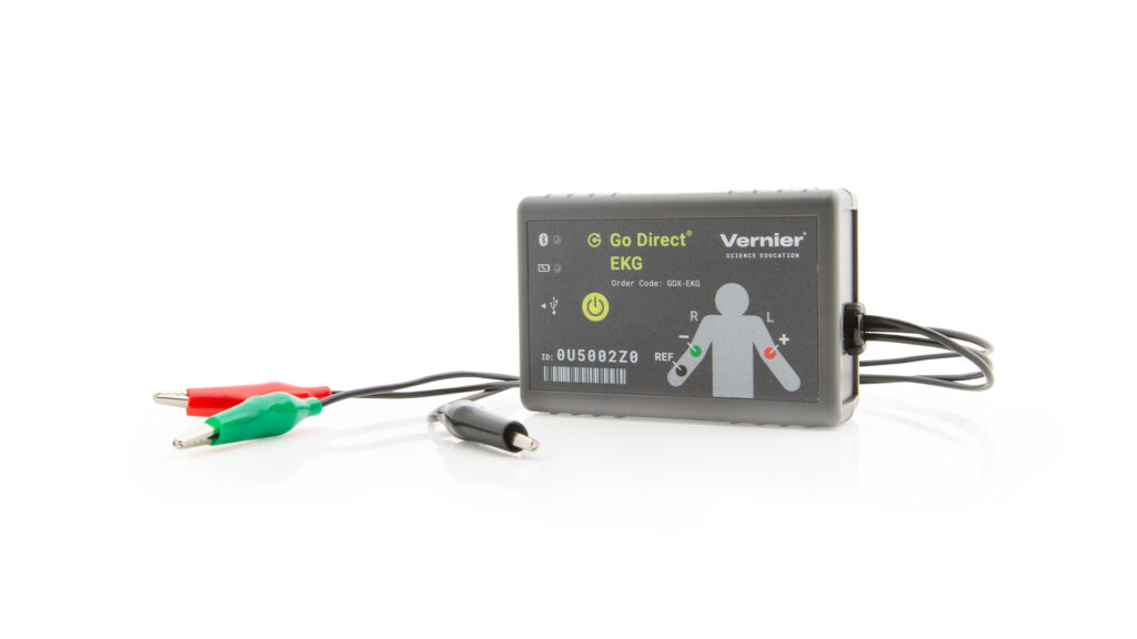
Go Direct EKG measures electrical activity in the heart and electrical signals produced during muscle contractions. The wireless options minimize the concern of cables getting caught and tangled during experiments. This sensor provides two separate outputs: one optimized for standard 3-lead EKG tracings and one optimized for surface EMG recordings.
Go Direct EKG can be used in a variety of experiments:
- Compare and measure students’ electrocardiogram (EKG/ECG) waveforms.
- Determine heart rate by examining the number of QRS waveforms over a period of time.
- Study contractions of muscles (EMG) in the arm, leg, or jaw.
- Correlate measurements of grip strength and electrical activity with muscle fatigue.
Note: Vernier products are designed for educational use. Our products are not designed nor are they recommended for any industrial, medical, or commercial process such as life support, patient diagnosis, control of a manufacturing process, or industrial testing of any kind.
What's Included
- Go Direct EKG
- One package of disposable electrodes (100)
- Micro USB Cable
Compatible Software
Choose a platform below to see its compatibility requirements.LabQuest
Interface LabQuest App LabQuest 3 Full support LabQuest 2 Full support 1 LabQuest Incompatible Compatibility Notes
Computers
Software Interface Graphical Analysis Graphical Analysis (Web App) No interface required Full support Full support LabQuest 3 Full support 1 Incompatible LabQuest 2 Full support 1 2 Incompatible Compatibility Notes
Chromebook
Software Interface Graphical Analysis (Web App) No interface required Full support iOS
Software Interface Graphical Analysis Graphical Analysis GW No interface required Full support Full support LabQuest 3 Full support 1 2 Full support 1 2 LabQuest 2 Full support 1 2 3 Full support 1 2 3 Compatibility Notes
Android
Software Interface Graphical Analysis Graphical Analysis GW No interface required Full support Incompatible LabQuest 3 Full support 1 2 Full support 1 LabQuest 2 Full support 1 2 3 Full support 1 3 Compatibility Notes
Python
Software Interface Python No interface required Full support Javascript
Software Interface Javascript No interface required Full support 1 Compatibility Notes
LabVIEW
Software Interface NI LabVIEW No interface required Full support
Quick Start: Vernier Graphical Analysis® and Bluetooth®
- Charge your sensor for at least 2 hours before first use.
- Turn on your sensor. The LED will blink red.
- Launch Graphical Analysis, then click Sensor Data Collection.
- Select your sensor from the list. The sensor ID is located on the sensor label near the bar code. Note: If you don’t see a list of available sensors, click WIRELESS. After selecting your sensor, click Pair.
- This is a multi-channel sensor. Click SENSOR CHANNELS and select the channel(s) you want to use.
- Click DONE. You are now ready to collect data.
WARNING: To avoid possible electric shock or personal injury, only use this product as designed. This product is designed to measure low-voltage, bio‑electric signals, such as EKGs and EMGs. It should never be connected to an electrical outlet.
Using other Vernier data-collection apps or want to connect via USB?
Visit www.vernier.com/start-go-direct
Note: This sensor also works with LabQuest 2 and LabQuest 3; it does not work with the original LabQuest.
Charging the Sensor
Connect Go Direct EKG to the included USB Charging Cable and any USB device for two hours.
You can also charge up to eight Go Direct EKG Sensors using our Go Direct Charge Station, sold separately (order code: GDX-CRG). An LED on each Go Direct EKG indicates charging status.
| Charging |
Orange LED next to the battery icon is solid while the sensor is charging. |
| Fully charged |
Green LED next to the battery icon is solid when the sensor is fully charged. |
Powering the Sensor
| Turning on the sensor |
Press button once. Red LED indicator next to the Bluetooth icon flashes when the unit is on. |
| Putting the sensor in sleep mode |
Press and hold button for more than three seconds to put into sleep mode. Red LED indicator next to Bluetooth icon stops flashing when sleeping. |
Connecting the Sensor
See the following link for up-to-date connection information:
Connecting via Bluetooth
| Ready to connect | Red LED next to the Bluetooth icon flashes when sensor is awake and ready to connect. |
| Connected | Green LED next to the Bluetooth icon flashes when sensor is connected via Bluetooth. |
Connecting via USB
| Connected and charging | Orange LED next to the battery icon is solid when the sensor is connected to Graphical Analysis via USB and the unit is charging. LED next to Bluetooth icon is off. |
| Connected, fully charged | Green LED next to the battery icon is solid when the sensor is connected to Graphical Analysis via USB and fully charged. LED next to Bluetooth icon is off. |
| Charging via USB, connected via Bluetooth |
Orange LED next to the battery icon is solid when the sensor is charging. Green LED next to the Bluetooth icon flashes. |
Identifying the Sensor
When two or more sensors are connected, the sensors can be identified by tapping or clicking Identify in Sensor Information.
Using the Product
Connect the sensor following the steps in the Quick Start section of the user manual.
Electrode Placement for EKGs
- Attach three electrode tabs to the subject as shown in Figure 1. Place a single patch on the inside of the right wrist, on the inside of the right upper forearm (distal to the elbow), and on the inside of the left upper forearm (distal to elbow).
- Connect the sensor clips to the electrode tabs as shown in Figure 1. Have the subject sit in a relaxed position in a chair with their forearms resting on their legs or on the arms of the chair.
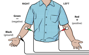
Figure 1
Electrode Placement for EMGs
To conduct EMGs, the red and green leads need to be placed on electrodes that are attached to the muscle of interest. The two leads are interchangeable for EMGs.
- Place two electrode tabs along the length of the muscle of interest. A third electrode tab should be placed above or below the nearest joint to serve as a ground. For example, to record from the muscles of the ventral forearm, attach three electrode tabs to the subject as shown in Figure 2. Two electrode tabs should be placed on the ventral forearm, 5 and 10 cm from the medial epicondyle with the ground electrode on the upper arm. Alternatively, the ground electrode can be placed on the wrist of the other arm to minimize movement artifacts.
- Attach the green and red leads to the electrode tabs on the muscle of interest. Attach the black lead to the ground electrode.
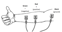
Figure 2
Channels
Go Direct EKG has five measurement channels:
- EKG
- Heart Rate
- EMG
- EMG Rectified
- Voltage
EKG
The EKG channel uses a low-pass filter that has been optimized for recording EKGs. This is the default channel that is active when the sensor is connected.
Heart Rate
The heart rate channel detects QRS waveforms and uses that data to calculate the heart rate in beats per minute (BPM). The sampling window for this calculation is 6 seconds. The value will update every second. This channel is not active by default when the sensor is connected.
EMG
The EMG channel uses a high-pass digital filter that has been optimized for recording EMGs. This channel is not active by default when the sensor is connected.
EMG Rectified
The EMG rectified channel returns the absolute value of the recorded EMG waveform. This makes all of the EMG deflections positive. This channel should be used for quantifying EMGs. This channel is not active by default when the sensor is connected.
Voltage
The voltage channel provides the unfiltered output from the sensor. This channel should be used when troubleshooting problems that occur when recording EMGs or EKGs. This channel is not active by default when connected to the sensor.
Videos
Calibrating the Sensor
The sensor is factory calibrated and cannot be calibrated by the user.
Specifications
|
Range |
±200 mV |
|
Resolution |
0.024 µV |
|
EKG channel settings |
|
|
EMG channel setting |
|
|
Heart rate calculation |
|
|
USB specification |
2.0 |
|
Wireless specification |
Bluetooth 4.2 |
|
Maximum wireless range |
30 m |
|
Battery |
300 mA Li-Poly |
|
Battery life (single full charge) |
~24 hours |
|
Battery life (long term) |
~500 full charge cycles (several years depending on usage) |
Care and Maintenance
Battery Information
The Go Direct EKG contains a small lithium-ion battery. The system is designed to consume very little power and not put heavy demands on the battery. Although the battery is warranted for one year, the expected battery life should be several years. Replacement batteries are available from Vernier (order code: GDX‑BAT-300).
Storage and Maintenance
To store the Go Direct EKG for extended periods of time, put the device in sleep mode by holding the button down for at least three seconds. The red LED will stop flashing to show that the unit is in sleep mode. Over several months, the battery will discharge but will not be damaged. After such storage, charge the device for a few hours, and the unit will be ready to go.
Exposing the battery to temperatures over 35°C (95°F) will reduce its lifespan. If possible, store the device in an area that is not exposed to temperature extremes.
Water Resistance
Important: Go Direct EKG is not water resistant and should never be immersed in water.
If water gets into the device, immediately power the unit down (press and hold the power button for more than three seconds). Disconnect the sensor and charging cable, and remove the battery. Allow the device to dry thoroughly before attempting to use the device again. Do not attempt to dry using an external heat source.
How the Sensor Works
The green and red leads are connected to a high-gain differential amplifier in the sensor that has been optimized for measuring bioelectric signals. The high-gain amplifier circuit that measures bioelectric signals is electrically isolated from an output circuit that sends information to our software. Electrical isolation makes the device safe for human use.
The electromyogram (EMG) is a graphic tracing of a muscle's electrical activity. The EMG is an extracellular surface recording of the action potentials that occur during a muscle contraction.
Muscle cells are polarized at rest. This means the cells have slightly unequal concentrations of ions across their cell membranes. An excess of positive sodium ions on the outside of the membrane causes the outside of the membrane to have a positive charge relative to the inside of the membrane. The inside of the cell is at a potential of about 90 millivolts (mV) less than the outside of the cell membrane. The 90 mV difference is called the resting potential. The typical cell membrane is relatively impermeable to the entry of sodium. However, stimulation of a muscle cell causes an increase in its permeability to sodium. Sodium ions migrate into the cell through the opening of voltage-gated sodium channels. This causes a change (depolarization) in the electrical field around the cell. This change in cell potential from negative to positive and back is a voltage pulse called an action potential. In muscle cells, action potential triggers muscle contractions.
Other ions and charged molecules are involved in the depolarization and repolarization of muscle. These include potassium, calcium, chlorine, and charged protein molecules. The sum action potential generated during the depolarization and repolarization of the cardiac muscle can be recorded by electrodes at the surface of the skin. A recording of the heart’s electrical activity is called an electrocardiogram (EKG).
The cells of the heart’s conducting system depolarize spontaneously. This spontaneous depolarization is most apparent in a cluster of cardiac-muscle cells embedded in the upper wall of the right atrium. This group of cells is called the pacemaker (also known as the sinoatrial or SA node). Depolarization of the pacemaker generates a current that leads to the depolarization of all other cardiac-muscle cells. The wave of depolarization travels from the right atrium to the left atrium quickly enough that both atria contract at essentially the same time.
The atria and the ventricles are isolated from each other electrically by connective tissue that acts like the insulation on an electric wire. The depolarization of the atria does not directly affect the ventricles. There is another group of cells in the right atrium, called the atrioventricular or AV node, which will conduct the depolarization of the atria down a special bundle of conducting fibers (called the Bundle of His) to the ventricles. In the muscle wall of the ventricles are Purkinje fibers, which are a special system of muscle fibers that bring depolarization to all parts of the ventricles almost simultaneously. This process causes a small time delay, so there is a short pause after the atria contract and before the ventricles contract. Because the cells of the heart muscle are interconnected, this wave of depolarization, contraction, and repolarization spreads across all of the connected muscle of the heart.
When a portion of the heart is polarized and the adjacent portion is depolarized, an electrical current is created that moves through the body. This current is greatest when one half of the connected portion of the heart is polarized and the adjacent half is not polarized. The current decreases when the ratio of polarized tissue to non-polarized tissue is less than one to one. The changes in these currents can be measured, amplified, and plotted over time. The EKG represents the summation of all the action potentials from the heart, as detected on the surface of the body. It does not measure the mechanical contractions of the heart directly.
The impulse originating at the SA node causes the atria to contract, forcing blood into the ventricles. Shortly after this contraction, the ventricles contract due to the signal conducted to them from the atria. The blood leaves the ventricles through the aorta and pulmonary artery. The polarity of the cardiac‑muscle cells returns to normal and the heart cycle starts again.
The Electrocardiogram
The electrocardiogram (EKG) is a graphic tracing of the heart’s electrical activity.
A typical tracing consists of a series of waveforms occurring in a repetitive order. These waveforms arise from a flat baseline called the isoelectric line. Any deflection from the isoelectric line denotes electrical activity.
The five major deflections on a normal EKG are designated by the letters P, Q, R, S, and T. One heart cycle is represented by a group of waveforms beginning with the P wave, followed by the QRS wave complex, and ending with the T wave.
The P wave represents the depolarization of the atria and is associated with their contraction. The QRS wave complex consists of three waves. The first negative deflection is the Q wave and is followed by a positive deflection called the R wave. The complex ends with a negative deflection known as the S wave. The QRS wave complex denotes depolarization of the ventricles and is associated with their contraction. Atrial repolarization occurs during the depolarization of the ventricles. For this reason, the waveform associated with atrial repolarization is undetectable on an EKG. The last wave is called the T wave, and is usually represented by a positive deflection. The T wave indicates ventricular repolarization.
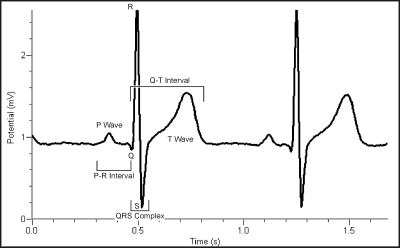
Figure 3
Electrical energy is also generated by skeletal muscle, and can be seen as muscle artifacts if your arm is moved while the EKG is attached. The sequence from P wave to P wave represents one heart cycle. The number of cycles in a minute is called the heart rate and is typically 55–75 beats per minute at rest.
Some typical times for portions of the EKG are
- P-R interval 0.12 to 0.20 seconds
- QRS interval less than 0.1 seconds
- Q-T interval less than 0.38 seconds
If your EKG does not correspond to the above numbers, do not be alarmed. These numbers represent typical averages and many healthy hearts have data that fall outside of these parameters. To read an EKG effectively takes considerable training and skill. This sensor is not intended for medical diagnoses.
Troubleshooting
- The most common problem is a poor connection between the electrodes, skin, and/or clips.
- Allow the electrode tabs to stabilize with the skin of the subject for at least 2 minutes before recording.
- Verify that the clips are firmly attached to the tabs of the electrodes.
- Electrode tabs should be fresh and can be used only once. Dry, old, or used electrode tabs will be problematic.
- Make sure the subject does not move during the recoding. For best results, make sure the subject is sitting and relaxed when recording EKGs.
- Try to limit all sources of electrical noise that can interfere with recordings. Make sure that computers, computer monitors, electrical outlets, phones, and other mobile devices are at least 1 m away from the sensor and subject.
- Make sure that the device being used to collect data from the sensor is not plugged into an electrical outlet.
For troubleshooting and FAQs, see www.vernier.com/til/4129
Repair Information
If you have watched the related product video(s), followed the troubleshooting steps, and are still having trouble with your Go Direct EKG, contact Vernier Technical Support at support@vernier.com or call 888-837-6437. Support specialists will work with you to determine if the unit needs to be sent in for repair. At that time, a Return Merchandise Authorization (RMA) number will be issued and instructions will be communicated on how to return the unit for repair.
Accessories/Replacements
| Item | Order Code |
|---|---|
|
CB-USB-MICRO |
|
|
CB-USB-C-MICRO |
|
| Go Direct 300 mAh Replacement Battery |
GDX-BAT-300 |
|
ELEC |
Warranty
Warranty information for this product can be found on the Support tab at www.vernier.com/gdx-ekg/#support
General warranty information can be found at www.vernier.com/warranty
Disposal
When disposing of this electronic product, do not treat it as household waste. Its disposal is subject to regulations that vary by country and region. This item should be given to an applicable collection point for the recycling of electrical and electronic equipment. By ensuring that this product is disposed of correctly, you help prevent potential negative consequences on human health or on the environment. The recycling of materials will help to conserve natural resources. For more detailed information about recycling this product, contact your local city office or your disposal service.
Battery recycling information is available at www.call2recycle.org
Do not puncture or expose the battery to excessive heat or flame.
 The symbol, shown here, indicates that this product must not be disposed of in a standard waste container.
Contact Support
Fill out our online support form or call us toll-free at 1-888-837-6437.