Shop
- Engineering
- Arduino
- Using Vernier Sensors with Arduino Guide
- Using Vernier Analog (BTA) Sensors with Arduino
Using Vernier Analog (BTA) Sensors with Arduino®
The majority of Vernier sensors are analog sensors. They typically operate on a 5 volt input, and output a voltage between 0 and 5 volts. The following sections explain how to use standard Vernier analog (BTA) sensors with Arduino microcontrollers.
Reading Analog Sensor Data Using Auto-ID
One of the best features about Vernier sensors is that they have a built-in autoID capability. You can automatically detect which sensor you are using and read a data point with just two simple commands.
Vernier.autoID();

Vernier.readSensor();
The Vernier.autoID() function is placed in the setup() portion of your sketch. This function checks for a standard analog (BTA) sensor connected to the Analog 1 port on the Vernier Arduino Interface Shield or an Analog Protoboard Adapter wired to Arduino pin A0 as explained in the Connecting Vernier Sensors to the Arduino Using a Breadboard section. (Note the VernierLib library does not support sensors plugged into the Analog 2 port on the Vernier Arduino Interface Shield or a second Analog Protoboard Adapter. To collect data from a second sensor you will need to manually calibrate raw voltage readings as described in Reading Raw Voltage.)
If a sensor is found in the Analog 1 port, it will read information about it, including:
- sensorName – the full name of the sensor found in the catalog
- shortName – an abbreviated name often used for labeling columns in data tables
- sensorUnits – a standard metric measurement
- sensorNumber – the product identifier
- calEquationType – the type of equation used for calibration. For most sensors,
- calEquationType = 1, indicating a linear calibration. A few sensors, such as temperature, require a more complex calibration equation.
- slope – a linear calibration variable
- intercept – a linear calibration variable
- cFactor – a variable used in nonlinear calibrations
- voltageID – the voltage read from sensors with built-in resistors
- page – the calibration information stored in sensors with memory chips
To access information about the sensor, you would use a statement like:
Serial.print (Vernier.sensorName());
This statement will print the full name of the sensor on the Serial Monitor. The Serial Monitor is a popup window that allows you to see data sent to and from your Arduino. You can access the Serial Monitor from the Tools menu.
The Vernier.readSensor() function will read one data point from the sensor connected to the Analog 1 port. To continuously read data from the sensor, you should put the function in the loop() portion of your sketch.
The sample sketch, VernierLibTutorialAnalogRead, will take sensor readings every half second and print the data with units to the Serial Monitor. You can try out different sensors simply by plugging in a new sensor and pressing the Reset button.
/* VernierLibTutorialAnalogRead (v2017)
 * This sketch reads a data point from a Vernier Analog (BTA)
 * sensor once every half second and prints the sensor reading
 * with units to the Serial Monitor.
 *
 * Plug the sensor into the Analog 1 port on the Vernier Arduino
 * Interface Shield or into an Analog Protoboard Adapter wired
 * to Arduino pin A0.
 */

#include "VernierLib.h" //include Vernier functions in this sketch
VernierLib Vernier; //create an instance of the VernierLib library


void setup() {
  Serial.begin(9600);
  while (!Serial);
  delay(4000);    //Need time for the Serial Monitor to become available
  Vernier.autoID(); //identify the sensor being used
}

void loop() {
  float sensorReading = Vernier.readSensor(); //read one data value
  Serial.print(sensorReading); //print data value
  Serial.print(" "); //print a space
  Serial.println(Vernier.sensorUnits()); //print units and skip to next line
  delay(500); //wait half second
}
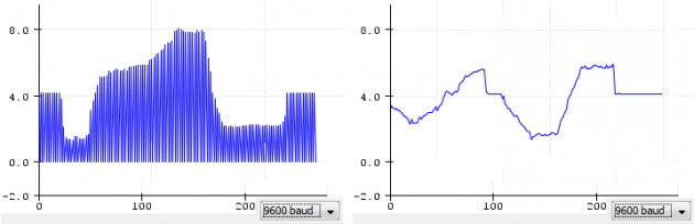
Graphing Sensor Data
In the previous section, we described how to display data on the Serial Monitor. The same sketch can be used to graph data on the Serial Plotter. The Serial Plotter is a Tool that comes pre-installed with the Arduino IDE. When the Serial Plotter is open, print commands will plot sensor data on the vertical Y axis. The scale automatically adjusts to fit your data. Note you cannot have the Serial Monitor and the Serial Plotter open at the same time.
The sample sketch, VernierLibTutorialAnalogGraph, will take sensor readings every half second and graph them to the Serial Plotter. Notice the optional command
Serial.println(0);
Adding this line will cause the graph to fill in with solid color. Eliminating this line will produce a simple line graph.
/* VernierLibTutorialAnalogGraph (v2017)
 * This sketch reads a data point from a Vernier Analog (BTA)
 * sensor once every half second and graphs the sensor data
 * to the Serial Plotter.
 *
 * Plug the sensor into the Analog 1 port on the Vernier Arduino
 * Interface Shield or into an Analog Protoboard Adapter wired
 * to Arduino pin A0. Open the Serial Plotter from the Tools
 * menu.
 */

#include "VernierLib.h" //include Vernier functions in this sketch
VernierLib Vernier; //create an instance of the VernierLib library

float sensorReading; //create global variable to store sensor reading

void setup() {
  Serial.begin(9600);
  while (!Serial);
  delay(4000);    //Need time for the Serial Monitor to become available
  Vernier.autoID(); //identify the sensor being used
}

void loop() {
  sensorReading = Vernier.readSensor(); //read one data value
  Serial.println(sensorReading); //graph data point
  //Serial.println(0); //optional command to create a filled-in plot
  delay(500); //wait half second
}
Controlling a Digital Line with Sensor Input
The Arduino contains a number of digital lines that can be used for controlling electronic devices, such as lights, buzzers, and motors. We designed the Vernier Arduino Interface Shield to include a blue LED connected to digital line 13 on the Arduino. You can use this LED as an output device (for example, a threshold indicator) in your projects. To access digital line 13 on the Arduino, you would put this statement in the setup portion of your sketch:
pinMode(13,OUTPUT);
To turn the LED on or off, use statements like:
digitalWrite(13, HIGH); //turns the LED on
digitalWrite(13, LOW); //turns the LED off
The sample sketch, VernierLibTutorialAnalogThreshold, will take sensor readings every half second and turn on the blue LED if the reading exceeds a threshold value. For example, if you have a Vernier Dual-Range Force Sensor plugged into the Analog 1 port, the blue LED will light up if the applied force exceeds 5 newtons. Note that this sketch will also work with an Analog Protoboard Adapter since the Arduino itself has an onboard LED wired to digital line D13.
/* VernierLibDemoAnalogThreshold (v2017)
 * This sketch reads a data point from a Vernier Analog (BTA)
 * sensor and turns on an LED (pin D13) if the sensor reading
 * exceeds a threshold value.
 *
 * Plug the sensor into the Analog 1 port on the Vernier Arduino
 * Interface Shield or into an Analog Protoboard Adapter wired
 * to Arduino pin A0.
 */

#include "VernierLib.h" //include Vernier functions in this sketch
VernierLib Vernier; //create an instance of the VernierLib library

float sensorReading; //create global variable to store sensor reading
float threshold = 5; //set threshold value for sensor

void setup() {
  Vernier.autoID(); //identify sensor being used
  pinMode(13,OUTPUT); //setup digital line 13 for output
}

void loop() {
  sensorReading = Vernier.readSensor(); //read one data value
  if (sensorReading > threshold) //check if threshold exceeded
  {
    digitalWrite(13,HIGH); //turn LED on
  }
  else
  {
    digitalWrite(13,LOW); //turn LED off
  }
  delay(500); //wait half second
}
Using Two Analog Sensors
The Vernier Arduino Interface Shield contains two analog (BTA) sockets that will allow you to take sensor readings from two different analog sensors at the same time. This feature gives you greater flexibility when creating your projects.
However, be aware that the VernierLib commands are only supported for sensors plugged into the Analog 1 port. To use two sensors, you must write a sketch that uses the VernierLib commands for the first sensor and the calibration equations (as explained in the Calibrating Analog Sensors section) for the second sensor. If you are using a temperature sensor, we recommend plugging it into the Analog 1 port as its calibration equations are quite cumbersome.
Note you can also take data from two sensors with two Analog Protoboard Adapters. Be sure to wire them as explained in the Connecting Vernier Sensors to the Arduino Using a Breadboard section.
Arduino® and
are trademarks of Arduino SA.