Attention: Safety Recall of Vernier Go Direct Charge Station. Click to learn more.

Shop

Calibrating Vernier Analog Sensors

There are times when you may want to custom-calibrate your sensor or use two analog sensors in your project. The VernierLib commands are only supported for analog (BTA) sensors plugged into the Analog 1 port on the Vernier Arduino® Interface Shield or into an Analog Protoboard Adapter wired to Arduino pin A0. You can use a second sensor in the Analog 2 port or in a second Analog Protoboard Adapter wired to Arduino pin A2, but you will need to manually calibrate your sensor to read data in either raw volts or sensor units. The following sections explain the equations used for each type of sensor.

Reading Raw Voltage

Arduinos have a built-in 10-bit analog-to-digital converter to read voltages. The voltage is read as a count in the range of 0 to 1023 with 0 representing 0 volts and 1023 representing 5 volts.

The sample sketch, VernierTutorialAnalogVoltage, will read the raw count from a Vernier analog sensor once every half second and convert it to a voltage value. This sketch assumes the sensor is plugged into the Analog 2 port on the Vernier Arduino Interface Shield or connected to an Analog Protoboard Adapter wired to Arduino pin A2 as explained in the Connecting Vernier Sensors to the Arduino Using a Breadboard section.

/* VernierTutorialAnalogVoltage (v2017)
 * This sketch reads the raw count from a Vernier Analog (BTA) 
 * sensor once every half second, converts it to a voltage, 
 * and prints both values to the Serial Monitor.
 * 
 * Plug the sensor into the Analog 2 port on the Vernier Arduino 
 * Interface Shield or into an Analog Protoboard Adapter wired 
 * to Arduino pin A2.
 */

float rawCount; //create global variable for reading from A/D converter (0-1023)
float voltage; //create global variable for voltage (0-5V)
 
void setup() {
  Serial.begin(9600);
  while (!Serial);
  delay(4000);    //Need time for the Serial Monitor to become available
}

void loop() {
  rawCount = analogRead(A2); //read one data value (0-1023)
  voltage = rawCount/1023*5; //convert raw count to voltage (0-5V)
  Serial.print(rawCount); //print raw count 
  Serial.print("\t"); //print a tab character
  Serial.println(voltage); //print voltage and skip to next line
  delay(500); //wait half second
}

Calibrating Sensors with Linear Calibrations

Fortunately, the vast majority of standard Vernier analog (BTA) sensors have linear calibrations. For these sensors, you need to convert from a raw voltage (described in the previous section) to the sensor value using the following equation:

sensorValue = slope * voltage + intercept

You can get the slope and intercept for Vernier sensors with a linear calibration from the sensor’s User Manual. You can download user manuals from any sensor’s web page or from the Vernier Support section of the website.

In the sensor’s User Manual, you will find a section called Specifications that lists the Stored Calibrations (slopes and intercepts) for that sensor. For example, the User Manual for the Vernier Dual-Range Force Sensor ±10N range lists:

Stored calibration

  • slope: -4.9 N/volt
  • intercept: 12.25 N

To convert Arduino voltages to forces in newtons, you would need to add variables for the slope and intercept, as well as the calibration equation. The sample sketch, VernierTutorialLinearCalibration, will read the raw count from a Vernier Dual-Range Force Sensor once every half second, convert it to a voltage, and then convert it to a sensor value. This sketch assumes the sensor is plugged into the Analog 2 port on the Vernier Arduino Interface Shield or connected to an Analog Protoboard Adapter wired to Arduino pin A2 as explained in the Connecting Vernier Sensors to the Arduino section.

/* VernierTutorialLinearCalibration (v2017)
 * This sketch reads the raw count from a Vernier Analog (BTA) 
 * sensor once every half second, and uses its algebraic slope 
 * and intercept to convert it to standard units.
 * 
 * Plug the sensor into the Analog 2 port on the Vernier Arduino 
 * Interface Shield or into an Analog Protoboard Adapter wired 
 * to Arduino pin A2.
 */

float rawCount; //create global variable for reading from A/D converter (0-1023)
float voltage; //create global variable for voltage (0-5V)
float sensorValue; //create global variable for sensor value
float slope = -4.9; //create global variable for slope for a Dual-Range Force Sensor +/-10N range
float intercept = 12.25; //create global variable for intercept for a Dual-Range Force Sensor +/-10N range
char *units = "N"; //create global variable for units for a Dual-Range Force Sensor


void setup() {
  Serial.begin(9600);
  while (!Serial);
  delay(4000);    //Need time for the Serial Monitor to become available
}

void loop() {
  rawCount = analogRead(A2); //read one data value (0-1023)
  voltage = rawCount/1023*5; //convert raw count to voltage (0-5V)
  sensorValue = slope*voltage+intercept; //convert to sensor value with linear calibration equation
  Serial.print(sensorValue); //print sensor value 
  Serial.print(" ");
  Serial.println(units); //print units and skip to next line
  delay(500); //wait half second
}

Calibrating Sensors with Nonlinear Calibrations

There are a few standard Vernier analog (BTA) sensors that have nonlinear calibrations. Calibration equations for thermistor temperature sensors (the Stainless Steel Temperature Probe and the Surface Temperature Sensor) are discussed in the next section, Calibrating Thermistor Temperature Sensors.

Calibration equations for other nonlinear sensors, such as the Ion-Selective Electrodes, Wide-Range Temperature Probe, and Ethanol Sensor can be found in their respective user manuals. Contact us if you have questions about these calibrations.

Calibrating Thermistor Temperature Sensors

Two of the most popular standard Vernier analog (BTA) sensors are the Stainless Steel Temperature Probe and the Surface Temperature Sensor. These sensors are electrically the same, but packaged differently. The thermistor on the Stainless Steel Temperature Probe is housed in a rugged stainless steel body, while the thermistor in the Surface Temperature Sensor is left exposed to give a faster response time. Both sensors use thermistors in series with a fixed resistor in a voltage divider situation. The voltage at the point between the fixed resistor and the thermistor can be measured by the Arduino and used to determine temperature.

The relationship between voltage and temperature is nonlinear, but it can be approximated within one degree Celsius using the Steinhart-Hart equation – a third order polynomial involving logarithmic calculations.

Temperature in Celsius = 1 / {A + B[ln(R)] + C[ln(R)]^3} – 273.15

where A =0.00102119, B = 0.000222468, C = 1.33342E-7, and R = the resistance of the thermistor. You can calculate the resistance of the thermistor using the equation:

{R_{T}} = ({\frac{V_{out}R_{1}}{V_{in}-V_{out}}})

Since both the Vernier Arduino Interface Shield and the Analog Protoboard Adapter were built with 15K precision resistors and the Arduino delivers a maximum voltage of 1024, the equation becomes:

Resistance = (Count*15000 / (1024-Count))

The sample sketch, VernierTutorialThermistor, uses this technique. This sketch assumes the temperature sensor is plugged into the Analog 2 port on the Vernier Arduino Interface Shield or connected to an Analog Protoboard Adapter wired to Arduino pin A2 as explained in the Connecting Vernier Sensors to the Arduino section. Note that the Steinhart-Hart equations have been put into a separate function called thermistor(). You will need to include the math.h library at the beginning of your sketch in order to access the natural log function.

/* VernierTutorialThermistor (v2017)
 * This sketch reads the temperature from a Vernier Stainless
 * Steel Temperature Probe or a Surface Temperature Sensor once
 * every half second.
 * 
 * We use the Steinhart-Hart equation (in the function
 * Thermistor) to calculate temperature from the raw voltage
 * reading. Because of the use of log functions in the
 * Steinhart-Hart equation, this sketch requires the math.h
 * library.
 * 
 * Plug the temperature sensor into the Analog 2 port on the 
 * Vernier Arduino Interface Shield or into an Analog 
 * Protoboard Adapter wired to Arduino pin A2.
 */

#include <math.h> //include library for log function

float rawCount; //create global variable for reading from A/D converter (0-1023)
float temperature; //create global variable for temperature in Celsius

void setup() {
  Serial.begin(9600);
  while (!Serial);
  delay(4000);   //Need time for the Serial Monitor to become available
}

void loop() {
  rawCount=analogRead(A2); //read one data value (0-1023)
  temperature=thermistor(rawCount); //calculate temperature
  Serial.println(temperature,1); // display temperature to one decimal)                               
  delay(500); //wait half second
}

//This function calculates temperature from raw count
float thermistor(int raw) {
  float resistor=15000; //initialize value of fixed resistor in Vernier shield
  float resistance; //create local variable for resistance
  float temp; //create local variable for temperature

  resistance=log(resistor*raw/(1024-raw)); //calculate resistance
  temp = 1 / (0.00102119 + (0.000222468 * resistance) + (0.000000133342 * resistance * resistance * resistance)); //calculate temperature using the Steinhart-Hart equation
  temp = temp - 273.15; //Convert Kelvin to Celsius                      
  return temp; //return the temperature
}

Calibrating Voltage Probes

There are two standard Vernier analog (BTA) sensors that use a different input line than the rest of the analog sensors. These are the Voltage Probe and the 30-Volt Voltage Probe. These two sensors use the +/-10 volt input line (SIG2) on the BTA connector.

The Arduino A/D converter can only handle voltages in the range of 0 to 5 volts. The Vernier Arduino Interface Shield has the necessary circuitry built in to change the sensor output from +/-10 volts to 0 to 5 volts. If you connect a sensor to the Analog 2 port on the shield, you can read voltage values with the sample sketch, VernierTutorialLinearCalibration. Substitute the following slope and intercept values:

Sensor used with the Vernier Arduino ShieldSlopeIntercept
Vernier Voltage Probe4–10
Vernier 30-Volt Voltage Probe15.41–40.35

If you are connecting the sensor to a Analog Protoboard Adapter wired to Arduino pin A2, you will need to build a voltage-divider circuit on a breadboard with two resistors and a diode to change the sensor output from +/-10 volts to 0 to 5 volts. 

A simple circuit is shown here.
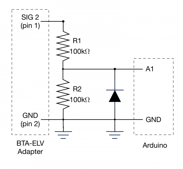
Simplified Circuit for Use with +/-10 Volt Sensors

Note that this circuit will not work with negative voltages; you need to keep the signal into the voltage probe positive. If you try to measure negative voltages the Arduino will read an incorrect voltage (0 V), but nothing will be damaged. You can read voltages with the VernierTutorialLinearCalibration sketch after substituting the following slope and intercept values:

Sensor used with the Vernier Analog Protoboard AdapterSlopeIntercept
Vernier Voltage Probe20
Vernier 30-Volt Voltage Probe6.3560

Arduino® and

Arduino Logo

are trademarks of Arduino SA.

SAVE/SHARE YOUR CART