Menu
Shop
- Engineering
- Arduino
- Using Vernier Sensors with Arduino Guide
- Projects and Ideas
- Controlling a Robotic Hand
Controlling a Robotic Hand
This is a variation of one of the projects on the Microsoft Hacking STEM Library. There they show you how to build a robotic hand out of cardboard, straws, and servo motors. They also show how to build a glove to control the robotic hand. They use the combination of Excel® software and an Arduino to make it all work together. The Microsoft project is great, but if you have some of our Vernier products, this version is simpler.
We have three different versions of this project, each one more complex and allowing more finger control, but requiring more hardware.
To do this version of the Robotic Hand project, follow these steps:
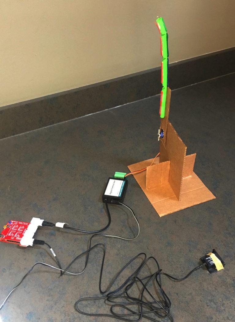
- Download the instructions from the Microsoft site as a PDF. Follow all the instructions in PART 1, Articulated Finger. This will show you how to build a finger out of a straw. When you come to PART 2, skip ahead several pages to the section labelled “Make the Robotic Finger”. This section shows you how to mount the finger on a cardboard stand and to install the servo motor. When you come to PART 3, you do not need the Microsoft instructions any more. Instead, follow these instructions to finish the project:
- Connect the Vernier Digital Control Unit to the Digital 2 connector on the Vernier Arduino Interface Shield.
- Connect the servo for the robotic finger to the three-pin connector on the DCU in Digital 2. Note that the ground connector is labeled on the connector. This wire is normally black on servo motors. Make sure you orient the connector correctly.
- Connect the power supply to the DCU.
- Connect the Low-g Accelerometer to the Analog 1 connector on the shield.
- Load the sketch VernierHandControl1 and try it out. Hold the accelerometer with the arrow pointed upward.
- Press the D12 button on the Arduino shield.
- Now try leaning the accelerometer so that the arrow is pointed at about 45 degrees from the vertical. The servo motor should rotate as you change the angle of the accelerometer. If you have made the connection of the string to the “horn” on the servo motor properly, the finger should bend forward.
- Once you have the finger moving nicely, use a rubber band or tape the accelerometer to the back of your finger, so that you can control the robotic finger with your finger.
- fingerStart
- the voltage from the accelerometer (in count read by the Arduino) when the accelerometer is pointed straight up.
- fingerStop
- the voltage from the accelerometer (in count read by the Arduino) when the accelerometer is pointed down.
Five-Finger Version Controlled by Two Accelerometers
This version of the project allows you to move a complete robotic hand, with the thumb controlled separately from the other four fingers.
It requires the following additional hardware (in addition to the equipment used for the single-finger version):
- a second Vernier Low-g Accelerometer
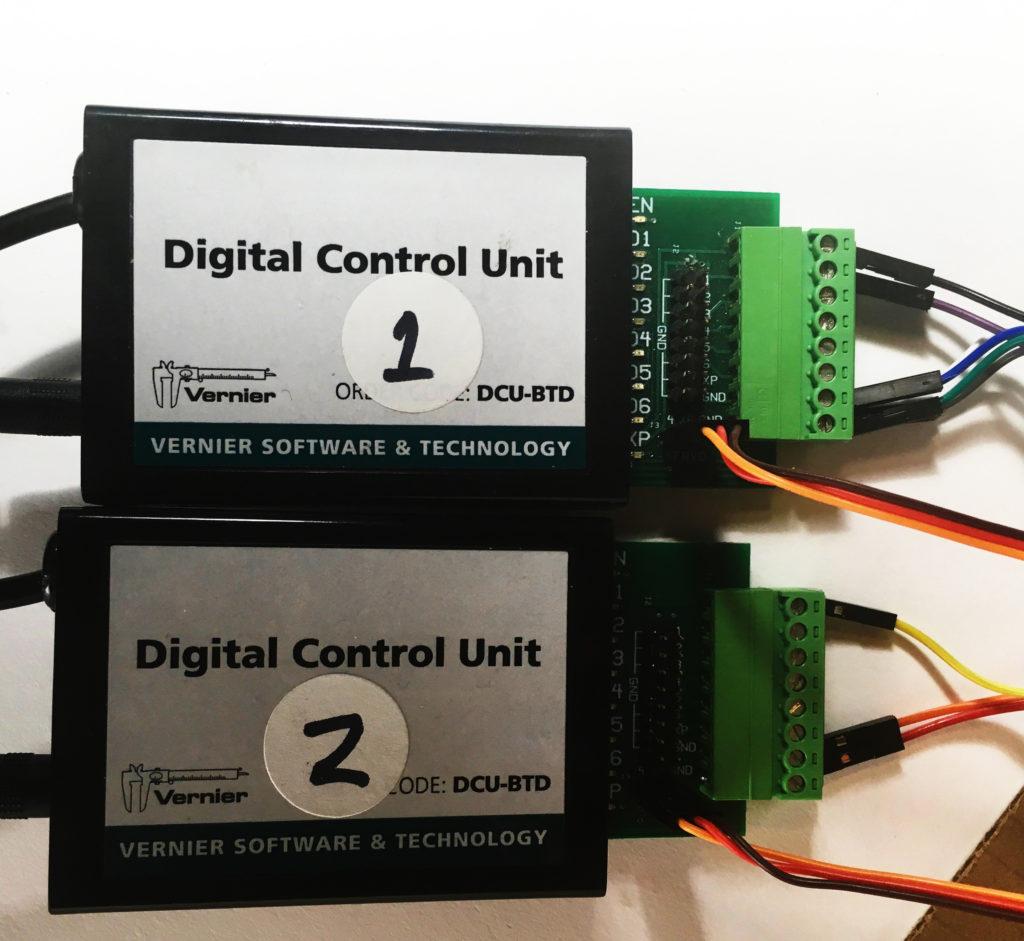
- a second Vernier Digital Control Unit
- a second 5-volt Vernier LabQuest Power Supply
- Four more “fingers”, with four servo motors, like the one used in the simpler project.
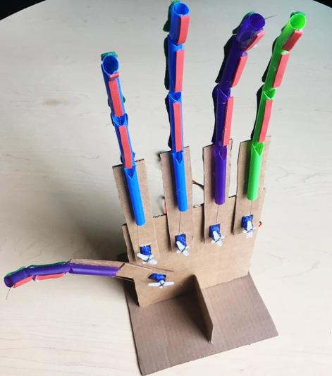
You need to complete the robotic hand, with four fingers and a thumb controlled by five servo motors. This is explained in the Microsoft instructions Part 4 in the section Complete Robotic Hand. You do not need to make the controlling glove or any of the wiring shown with in this section. You do not need a breadboard. Instead, follow these instructions:
- Connect one DCU to the Digital 1 connector on the Vernier Arduino Interface Shield. Connect the second DCU to the Digital 2 connector.
- Connect the five servo motors for the hand to the DCUs as follows:
- Connect the thumb servo to the three-pin connector on the DCU in Digital 1 (Arduino line D5). Be sure the black wire is connected to the ground connector.
- Connect the index finger servo to the three-pin connector on the DCU in Digital 2 (Arduino line D9).
- Use short wire segments to connect the remaining 3 servo motors.
- Connect the smallest finger (pinky) servo to the screw terminal 1 connector (Arduino line D2) on the DCU in Digital 1. It should also be connected to the power and GND screw terminals.
- Connect the ring finger servo to the screw terminal 2 connector (Arduino line D3) on the DCU in Digital 1. It should also be connected to the power and GND screw terminals.
- Connect the middle finger servo to the screw terminal 1 connector (Arduino line D6) on the DCU in Digital 2. It should also be connected to the power and GND screw terminals.
- Connect a power supply to each DCU.
- Connect a Low-g Accelerometer to the Analog 1 connector on the shield. This will control the thumb.
- Connect the second Low-G Accelerometer to the Analog 2 connector on the shield. This will control all of the fingers.
Load the sketch VernierHandControl2 and try it out. Hold the two accelerometer with the arrows pointed upward. Press the D12 button on the shield. Now try leaning the thumb-control accelerometer so that the arrow is pointed at about 45 degrees from the vertical. The thumb servo motor should rotate as you change the angle of the accelerometer. If you have made the connection of the string to the “horn” on the servo motor properly, the thumb should articulate. Remember that the accelerometers we are using measure their orientation with respect to the vertical. Make sure that when you move your thumb the accelerometer moves so it is pointing somewhat downward.
Now, try leaning the finger-control accelerometer so that the arrow is now pointed at about 45 degrees from the vertical. All four finger servo motors should rotate as you change the angle of the accelerometer. If you have made the connection of the string to the “horn” on the servo motors, the fingers should articulate.
There are two ways to tune the finger motions. Easiest is to pull the servo horns off and change their orientation to adjust the amount of pull on the strings. More complicated is changing the values of the following constants in the sketch: thumbStart, fingerStart, thumbStop, fingerStop. These numbers can be changed to correct for minor differences in the reading from individual accelerometers. They are used in the map statements. Here is what they represent:
- thumbStart
- the voltage from the thumb-control accelerometer (in count read by the Arduino) when that accelerometer is pointed straight up.
- fingerStart
- the voltage from the finger-control accelerometer (in count read by the Arduino) when that accelerometer is pointed straight up.
- thumbStop
- the voltage from the thumb-control accelerometer (in count read by the Arduino) when that accelerometer is pointed straight down.
- fingerStop
- the voltage from the finger-control accelerometer (in count read by the Arduino) when that accelerometer is pointed down.
Once you have the fingers and thumb moving nicely, mount the accelerometers on the back of a glove so the project is ready to demonstrate.
Power supply connected to each DCU.
Five-Finger Version Controlled by Four Accelerometers
This version of the project allows you to move a complete robotic hand, with the fingers controlled more individually.
It requires the following additional hardware (in addition to the equipment used for the Five-Finger Version Controlled by Two Accelerometers project):
- a second SparkFun/Vernier Redboard (or an Arduino Uno or equivalent)
- a second Vernier Arduino Shield
- two additional Low-g Accelerometers

For this project, the servo motors are connected to the DCUs the same way they were in the Five-Finger Version Controlled by Two Accelerometers project. This time, the second DCU is connected to and controlled by a second Arduino. Two additional accelerometers are used with this Arduino to control the index and middle finger.
Assuming you have already built the hand with five servo motors connected as explained in the Five-Finger Version Controlled by Two Accelerometers project, here are the changes you need to do for this version of the project:
- Connect a third accelerometer to Analog 1 of the second Arduino. It will control the index finger
- Connect a fourth accelerometer to Analog 2 of the second Arduino. It will control the middle finger
- Move the DCU that was connected to the Digital 2 port of the original Arduino to the Digital 2 port of a second Arduino. Do not change the wiring from the servo motors to the DCUs.
- Load the sketch named VernierHandControl4-1 on the Arduino connected to the thumb. It is a slightly revised version of the programs used on other versions of this project.
- Load the sketch named VernierHandControl4-2 on the Arduino connected to the index finger. It is also a slightly different version.
- Try out each Arduino separately. First try the Arduino connected to the DCU controlling the thumb. It should also control the thumb and the ring and smallest finger, which move together. Hold the two accelerometers connected to this Arduino with the arrows pointed upward. Press the D12 button on the shield. Now, try leaning each accelerometer so that the arrow is pointed at about 45 degrees from the vertical. The corresponding servo motor should rotate as you change the angle of the accelerometer. If you have made the connection of the string to the “horn” on the servo motor properly, the thumb or fingers should articulate.
You can tune the finger motions by repositioning the servo horns or by changing “start” and “stop” constants in the code.
If this is all working, try out the other Arduino. It should control the index and middle fingers.
Once you have the fingers and thumb moving nicely, mount the accelerometers on the back of a glove so the project is ready to demonstrate. Remember that the accelerometers we are using measure their orientation with respect to the vertical. Make sure that when you move a finger of your hand the accelerometer moves so it is pointing somewhat downward.
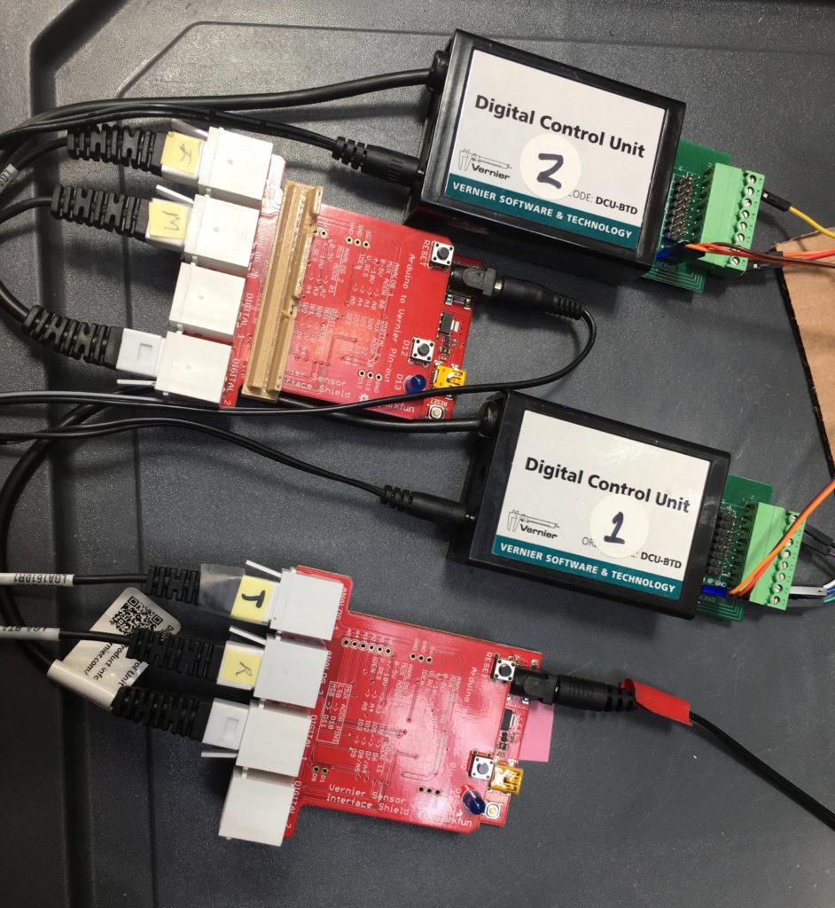
Arduino, DCU, and accelerometer connections