Introduction
An electrocardiogram (ECG or EKG) records electrical events that occur within the heart. In a healthy heart, a natural pacemaker in the right atrium (the sinoatrial node) initiates an electrical sequence. This impulse passes down natural conduction pathways between the atria to the atrioventricular node and from there to both ventricles. The natural conduction pathways facilitate orderly spread of the impulse and coordinated contraction of first the atria, then the ventricles. The electrical journey creates unique deflections in the EKG that tell a story about heart function and health (see Figure 1).

Figure 1
Even more information is obtained by looking at the story from different angles, which is accomplished by placing electrodes in different arrangements on the body. Each arrangement is called a lead. Each lead reveals unique information based on the lead’s orientation relative to the axis of the heart.
The heart’s axis tends to vary with general body shape, age, and other factors. In this experiment, you will use an EKG sensor to make graphical recordings of the heart’s electrical activity using several different electrode positions to create three different leads. For each lead, you will connect the three EKG electrodes in a specific pattern.
Lead I
For Lead I, the electrodes are connected as follows:
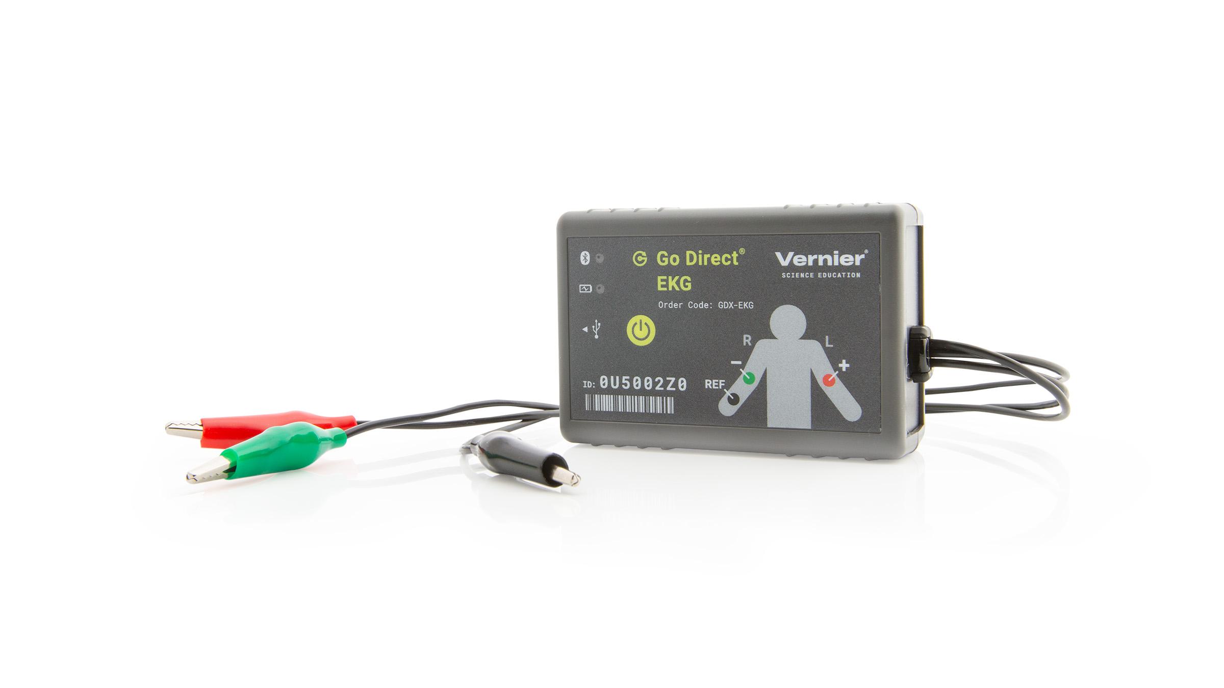
- Green (negative) electrode: Right upper arm or wrist
- Red (positive) electrode: Left upper arm or wrist
- Black (reference) electrode: Inside of left ankle (reference point for the isoelectric line)
Drawing an imaginary line between the red and green electrodes shows that this lead measures the polarity changes across the chest, above the heart, and parallel to the shoulders.
Lead II
For Lead II, the electrodes are connected as follows:
- Green (negative) electrode: Right upper arm or wrist
- Red (positive) electrode: Left inner thigh or inside of left ankle
- Black (reference) electrode: Left upper arm or wrist (reference point for the isoelectric line)
Drawing an imaginary line between the red and green electrodes yields an oblique line from the right shoulder towards the left leg. Lead II generally gives the greatest variation of impulse and is the EKG usually shown in movies and text books.
Lead III
For Lead III, the electrodes are connected as follows:
- Green (negative) electrode: Left upper arm or wrist
- Red (positive) electrode: Left inner thigh or inside of left ankle
- Black (reference) electrode: Right upper arm or wrist (reference point for the isoelectric line)
This arrangement of the red and green electrodes yields an imaginary line from the left shoulder to the left leg.
Einthoven’s Triangle
If you connect the three electrodes in a lead with imaginary lines, the lines would make a triangle. This triangle is called the Einthoven’s triangle. The measured intensity of voltage on its three sides can be used to study heart functions and anatomy. You can make an approximation of the axis of your heart; that is, the orientation of the centerline of the mass of your heart.

Figure 2
By comparing results from Lead I, Lead II, and Lead III recordings, you will determine which lead yields the maximum R wave amplitude. If the maximum R wave is with Lead I, then the axis of your heart is approximately at 0 degrees as measured from the horizontal and your left. If the maximum R wave is with Lead II, then the axis of the heart is approximately 60 degrees down from the horizontal and to the left.
If the maximum R wave is with Lead III, then the axis is approximately 120 degrees from the horizontal and your left. You can make a further refinement in your estimate by noting the relative proportion of R wave strength between the two leads with the largest R wave.
If the Lead II and the Lead III R waves are about equal, then the axis is about halfway between the 60 degree angle and the 120 degree angle. You could therefore estimate the axis of the heart to be nearly vertical.
Important: The equipment used in this experiment is for educational purposes only and should not be used to diagnose medical conditions.
Objectives
- Obtain graphical representation of the electrical activity of the heart (EKG).
- Obtain graphical representation of a pressure pulse from the brachial artery.
- Calculate the transit time of a pressure pulse from the heart to the brachial artery.
Sensors and Equipment
This experiment features the following sensors and equipment. Additional equipment may be required.
Ready to Experiment?
Ask an Expert
Get answers to your questions about how to teach this experiment with our support team.
- Call toll-free: 888-837-6437
- Chat with Us
- Email support@vernier.com
Purchase the Lab Book
This experiment is #5 of Human Physiology Experiments: Volume 2. The experiment in the book includes student instructions as well as instructor information for set up, helpful hints, and sample graphs and data.


