Go Direct® Cyclic Voltammetry System User Manual
Order Code: GDX-CVS
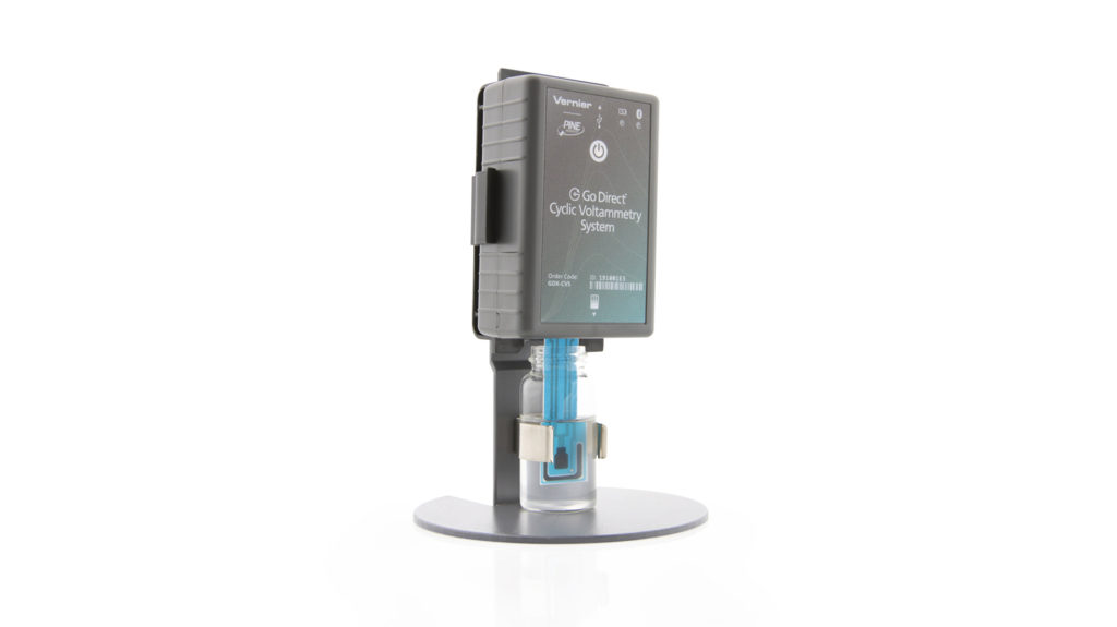
Go Direct Cyclic Voltammetry System is a potentiostat that students can use to easily control and apply potential to a chemical system and measure the response as electrical current. It has three modes of data collection: cyclic voltammetry, bulk electrolysis, and open-circuit potentiometry. It includes a stand, scintillation vials, and disposable screen-printed electrodes. Free Vernier Instrumental Analysis® software and free experiments are available for download.
Note: Vernier products are designed for educational use. Our products are not designed nor are they recommended for any industrial, medical, or commercial process such as life support, patient diagnosis, control of a manufacturing process, or industrial testing of any kind.
What's Included
- Go Direct Cyclic Voltammetry System
- Screen printed electrodes (25)
- Scintillation vials (4)
- Cyclic voltammetry system stand
- Electrochemistry Experiments with the Go Direct Cyclic Voltammetry System (free e-book download)
- Micro USB Cable
Compatible Software
Choose a platform below to see its compatibility requirements.LabQuest
Interface LabQuest App LabQuest 3 Full support LabQuest 2 Full support 1 LabQuest Incompatible Compatibility Notes
Computers
Software Interface Instrumental Analysis No interface required Full support Chromebook
Software Interface Instrumental Analysis No interface required Full support iOS
Software Interface Instrumental Analysis No interface required Full support Android
Software Interface Instrumental Analysis No interface required Full support
Quick Start: Vernier Instrumental Analysis and Bluetooth®
- Charge your sensor for at least 2 hours before first use.
- Turn on your sensor. The LED will blink red.
- If using Vernier Instrumental Analysis, launch the app and then click Voltammetry. If using LabQuest®, turn it on and choose Wireless Device Setup > Go Direct from the Sensors menu.
- Select your sensor from the list. The sensor ID is located on the sensor label near the bar code. Note: If you don’t see a list of available sensors, click WIRELESS. After selecting your sensor, click Pair.
- Click DONE. You are now ready to collect data.
Using other Vernier data-collection apps or want to connect via USB?
Visit www.vernier.com/start-go-direct
Note: This sensor also works with LabQuest 2 and LabQuest 3; it does not work with the original LabQuest.
Connecting the Sensor
See the following link for up-to-date connection information:
Connecting via Bluetooth
| Ready to connect | Red LED next to Bluetooth icon flashes when the sensor is awake and ready to connect. At the same time, the red LED next to the power icon is steady. |
| Connected | Green LED next to Bluetooth icon flashes when the sensor is connected via Bluetooth. |
Connecting via USB
| Connected | Red LED next to power icon on steady when sensor is connected to Graphical Analysis via USB. LED next to Bluetooth icon off. |
Powering the Sensor
| Turning on the sensor |
Red LED is on steady when connected to AC power. |
| Putting the sensor in sleep mode |
Red LED is off when disconnected from AC power. |
Using the Product with Instrumental Analysis
Preparing your Instrument for Data Collection
- Insert a screen-printed electrode (SPE) into the SPE connector on the Cyclic Voltammetry System (see Figure 1). Avoid touching the black electrode part of the SPE.
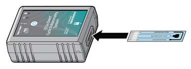
Figure 1
- Fill the scintillation vial about halfway full (~10 mL) with your sample. Insert the scintillation vial into the clip on the stand. Carefully guide the Cyclic Voltammetry System with the SPE attached downward into the vial and snap the instrument into place, as shown in Figure 2.
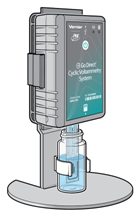
Figure 2
Selecting Experiment Type
The three options for Experiment Types are
- Cyclic Voltammetry
- Bulk Electrolysis
- Open Circuit Potentiometry
- Connect the sensor following the steps in the Quick Start section of this user manual. The Voltammetry Settings menu should be open automatically.
- Select the desired experiment type. Cyclic Voltammetry is selected by default. The default parameters are appropriate for measuring a cyclic voltammogram for common samples in a buffer solution. You may want to adjust these settings according to the student instructions in the Electrochemistry Experiments with the Go Direct Cyclic Voltammetry System e-book.
- Click or tap Collect to begin data collection. The run will stop automatically or you can choose to end it early.
- Name your sample appropriately. To do this, click or tap on the y-axis label. Click or tap on Data Set Options next to the data set you wish to rename. Click or tap Rename Data Set. Enter a name for the sample and click or tap Rename.
- Analyze the voltammogram by selecting the desired peak. Click or tap Graph Tools,
 , and choose View Statistics. You may also wish to analyze your data using the peak integral function also located under the Graph Tools menu.
 - When you are ready to change your sample, carefully remove the Cyclic Voltammetry System from the stand by pulling back on the top tab (Figure 3).
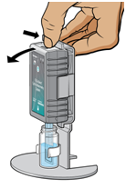
Figure 3
- With the SPE still inserted in the Cyclic Voltammetry System, rinse the SPE with buffer solution, and dry it by gently blotting the electrode surface with a piece of paper towel. Important: Do not invert the Cyclic Voltammetry System with a damp SPE attached. You want to avoid getting liquid inside the SPE connector.
-
Repeat Steps 2–7 for as many samples as you test. To change the parameters between runs, click or tap Voltammetry Settings,
 .
. - When you are finished with you experiment, discard the solution and SPE as instructed. Click or tap on the File Menu to Save or Export your data.
Changing the Settings in Instrumental Analysis
Click or tap the slider, , to show the Voltammetry Settings dialog. You will set the Experiment type you wish to perform here. There are multiple parameters listed in the dialog box that will vary based on the experiment you have selected.
Cyclic Voltammetry
In this experiment type, the electrode potential ramps linearly with time in a preset waveform, often through the electroactive species’ standard potential, which allows for the investigation of the resulting electrochemical species generated at the electrode surface. The rate of voltage changes over time during each of the segments in the waveform, known as the experiment's sweep rate. The potential is measured between the working electrode and the reference electrode on the SPE, while the current is measured between the working electrode and the counter electrode on the SPE.
- Number of Segments: You will be able to choose from a 1-, 2-, or 3-segment CV. This is the number of segments in the potentiostat’s waveform. The number of segments determines the number of potentials you must set. One‑segment will be linear sweep voltammetry with simply an initial and final potential setting. A two-segment CV will have an initial and final potential, along with one switching potential. A three-segment CV will have an initial and final potential, along with two switching potentials.
- Potentials: You will need to set each potential to dictate the potentiostat’s waveform, including the Initial and Final Potentials, along with applicable Switching Potentials. To illustrate the importance of these settings, let us use the example of a 3-segment CV. First, set the number of segments to 3. The Initial Potential is the potential at which you wish the voltammogram to start. In this example, we will set it to 0 mV. From here, the potential must sweep in either a negative or positive direction from the initial potential; therefore, in this case, Switching Potential 1 cannot be 0 mV. Setting Switching Potential 1 to +750 mV means the CVS will sweep in a positive direction from 0 mV to +750 mV. Note: You cannot sweep more than 2000 mV in one direction and it is not recommended to sweep more than 1600 mV in one direction. From Switching Potential 1, the CVS must sweep in a positive or negative direction to Switching Potential 2. Setting Switching Potential 2 to –500 mV means the CVS will now sweep from +750 mV to -500 mV. The Final Potential is where the CVS will conclude the experiment acquisition.
- Sweep Rate: The Sweep Rate is the rate at which the individual segments sweeps will occur in mV/s.
- Current Range: The Current Range sets the allowed current range for the CV. The High Current Range is ±1000 μA, Medium is ±100 μA, Low is ±10 μA, and Lowest is ±1 μA. Setting to a lower current range will increase resolution of your CV; however, if the current range is set too low, the CV cannot proceed. Note: The range values are not absolute, you may be able to get some additional current on any particular setting but this will vary from instrument to instrument.
Bulk Electrolysis
In this setting, the potentiostat holds the potential of the working electrode at one value and measures the resulting current over time. In this type of experiment, the analyte is converted from its original oxidation state to a new oxidation state either through reduction or oxidation. Analyzing the resulting data can help determine the electric charge passed over time. The experimental parameters to set are the potential (mV), rate (s), and duration (s).
Open-Circuit Potentiometry
This experiment is a passive experiment whereby the counter electrode circuitry of the potentiostat is bypassed. In this mode, only the resting potential measured between the reference and working electrode is measured. This is not to say that the chemical system is at equilibrium. In fact, some systems may be far from equilibrium and their passive potential changes as a function of homogeneous reactions. What makes OCP unique is that is a purely electrolytic measurement, thermodynamically. The experimental parameters to set are the rate (s) and duration (s).
Using the Internal Resistor
The system contains an internal resistor that is a 1000 Ω resistor. Click or tap the [+] for the CVS and enable the Use Internal Resistor option. You can engage this internal resistor to troubleshoot the instrument or to do a demonstration of Ohm’s law as described in our experiment titled "Cyclic Voltammetry Basics: Ohm’s Law". Note: Do not attach an external SPE when using the Internal Resistor.
Cleaning your SPE
While this is not common, you may wish to clean your SPE before running certain experiments. We recommend running a 2-segment CV with Initial Potential of 1000 mV, Switching Potential 1 of –1000 mV, and Final Potential of 1000 mV. Set the Sweep Rate to 100 mV/s and Current Range to High. You can choose to repeat it if you wish. The recommended cleaning solution for most applications is 0.1 M H2SO4.
Using the Product with LabQuest App
Preparing your Instrument for Data Collection
- Insert a screen-printed electrode (SPE) into the SPE connector on the Cyclic Voltammetry System (see Figure 1). Avoid touching the black electrode part of the SPE.
Figure 1
- Fill the scintillation vial about halfway full (~10 mL) with your sample. Insert the scintillation vial into the clip on the stand. Carefully guide the Cyclic Voltammetry System with the SPE attached downward into the vial and snap the instrument into place, as shown in Figure 2.
Figure 2
Selecting Experiment Type
The three options for Experiment Types are
- Cyclic Voltammetry
- Bulk Electrolysis
- Open Circuit Potentiometry
- Connect the sensor following the steps in the Quick Start section of this user manual. Select Data Collection from the Sensors menu to access the Voltammetry Settings menu.
- Select the desired experiment type. Cyclic Voltammetry (shortened to Voltammetry) is selected by default. The default parameters are appropriate for measuring a cyclic voltammogram for common samples in a buffer solution. You may want to adjust these settings according to the student instructions in the Electrochemistry Experiments with the Go Direct Cyclic Voltammetry System e-book.
- Click or tap Collect to begin data collection. The run will stop automatically or you can choose to end it early.
- Name your sample appropriately. To do this, navigate to the table screen. Tap (LabQuest 2) or double-tap (LabQuest 3) on the column header of the data set you wish to rename. Enter a name for the sample and tap Done.
- From the Graph menu, analyze the voltammogram by selecting the desired peak. From the Analyze menu, choose Statistics. You may also wish to analyze your data using the integral function also located under the Analyze menu.
- When you are ready to change your sample, carefully remove the Cyclic Voltammetry System from the stand by pulling back on the top tab (Figure 3).
Figure 3
- With the SPE still inserted in the Cyclic Voltammetry System, rinse the SPE with buffer solution, and dry it by gently blotting the electrode surface with a piece of paper towel. Important: Do not invert the Cyclic Voltammetry System with a damp SPE attached. You want to avoid getting liquid inside the SPE connector.
- Repeat Steps 2–7 for as many samples as you test. To change the parameters between runs, tap Data Collection from the Sensors menu on the Meter screen.
- When you are finished with you experiment, discard the solution and SPE as instructed. Click or tap on the File Menu to Save or Export your data.
Changing the Settings in LabQuest App
On the Meter screen, select Data Collection from the Sensors menu. This will show the Voltammetry Settings dialog. You will set the Experiment type you wish to perform here. There are multiple parameters listed in the dialog box that will vary based on the experiment you have selected.
Cyclic Voltammetry
In this experiment type, the electrode potential ramps linearly with time in a preset waveform, often through the electroactive species’ standard potential, which allows for the investigation of the resulting electrochemical species generated at the electrode surface. The rate of voltage changes over time during each of the segments in the waveform, known as the experiment's sweep rate. The potential is measured between the working electrode and the reference electrode on the SPE, while the current is measured between the working electrode and the counter electrode on the SPE.
- Number of Segments: You will be able to choose from a 1-, 2-, or 3-segment CV. This is the number of segments in the potentiostat’s waveform. The number of segments determines the number of potentials you must set. One‑segment will be linear sweep voltammetry with simply an initial and final potential setting. A two-segment CV will have an initial and final potential, along with one switching potential. A three-segment CV will have an initial and final potential, along with two switching potentials.
- Potentials: You will need to set each potential to dictate the potentiostat’s waveform, including the Initial and Final Potentials, along with applicable Switching Potentials. To illustrate the importance of these settings, let us use the example of a 3-segment CV. First, set the number of segments to 3. The Initial Potential is the potential at which you wish the voltammogram to start. In this example, we will set it to 0 mV. From here, the potential must sweep in either a negative or positive direction from the initial potential; therefore, in this case, Switching Potential 1 cannot be 0 mV. Setting Switching Potential 1 to +750 mV means the CVS will sweep in a positive direction from 0 mV to +750 mV. Note: You cannot sweep more than 2000 mV in one direction and it is not recommended to sweep more than 1600 mV in one direction. From Switching Potential 1, the CVS must sweep in a positive or negative direction to Switching Potential 2. Setting Switching Potential 2 to –500 mV means the CVS will now sweep from +750 mV to –500 mV. The Final Potential is where the CVS will conclude the experiment acquisition.
- Sweep Rate: The Sweep Rate is the rate at which the individual segments sweeps will occur in mV/s.
- Current Range: The Current Range sets the allowed current range for the CV. The High Current Range is ±1000 μA, Medium is ±100 μA, Low is ±10 μA, and Lowest is ±1 μA. Setting to a lower current range will increase resolution of your CV; however, if the current range is set too low, the CV cannot proceed. Note: The range values are not absolute, you may be able to get some additional current on any particular setting but this will vary from instrument to instrument.
Bulk Electrolysis
In this setting, the potentiostat holds the potential of the working electrode at one value and measures the resulting current over time. In this type of experiment, the analyte is converted from its original oxidation state to a new oxidation state either through reduction or oxidation. Analyzing the resulting data can help determine the electric charge passed over time. The experimental parameters to set are the potential (mV), rate (s), and duration (s).
Open-Circuit Potentiometry
This experiment is a passive experiment whereby the counter electrode circuitry of the potentiostat is bypassed. In this mode, only the resting potential measured between the reference and working electrode is measured. This is not to say that the chemical system is at equilibrium. In fact, some systems may be far from equilibrium and their passive potential changes as a function of homogeneous reactions. What makes OCP unique is that is a purely electrolytic measurement, thermodynamically. The experimental parameters to set are the rate (s) and duration (s).
Using the Internal Resistor
The system contains an internal resistor that is a 1000 Ω resistor. Click or tap the [+] for the CVS and enable the Use Internal Resistor option. You can engage this internal resistor to troubleshoot the instrument or to do a demonstration of Ohm’s law as described in our experiment titled "Cyclic Voltammetry Basics: Ohm’s Law". Note: Do not attach an external SPE when using the Internal Resistor.
Cleaning your SPE
While this is not common, you may wish to clean your SPE before running certain experiments. We recommend running a 2-segment CV with Initial Potential of 1000 mV, Switching Potential 1 of –1000 mV, and Final Potential of 1000 mV. Set the Sweep Rate to 100 mV/s and Current Range to High. You can choose to repeat it if you wish. The recommended cleaning solution for most applications is 0.1 M H2SO4.
Specifications
|
Methods |
Cyclic Voltammetry Bulk Electrolysis Open Circuit Potentiometry |
|
USB specification |
2.0 |
|
Wireless specification |
Bluetooth 4.2 |
|
Maximum wireless range |
30 m |
|
Dimensions |
9 cm length, 6 cm height, 3 cm depth |
|
Current ranges (4 total) |
High: ±1000 μA Medium: ±100 μA Low: ±10 μA Lowest: ±1 μA |
|
Operational Potential Range |
–2000 mV to +2000 mV vs REF |
|
Practical Potential Range (This is typical of using the Vernier screen-printed electrodes in aqueous solutions. Results may vary when using other electrodes and solvents.) |
–1200 mV to +1200 mV vs REF |
Cyclic Voltammetry
- Minimum Sweep Rate: 1 mV/s
- Maximum Sweep Rate: 2000 mV/s
- Recommended Maximum Sweep Span: 1600 mV
- Available Number of Sweep Segments: 1, 2, or 3
Bulk Electrolysis
- Minimum Sampling Rate: 2 samples per second
- Maximum Sampling Rate: 200 samples per second
Open Circuit Potential
- Minimum Sampling Rate: 2 samples per second
- Maximum Sampling Rate: 200 samples per second
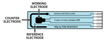
How the Sensor Works
The Go Direct Cyclic Voltammetry System is a potentiostat that uses a screen-printed electrode as its three-electrode system. The three electrodes are labeled below and include the working electrode, the reference electrode, and the counter electrode.
The Go Direct Cyclic Voltammetry System potentiostat allows you to measure the rate of an electron transfer reaction or redox reaction. In this system, you make a circuit out of a solution containing a molecule of interest (analyte), change the voltage (electrode potential) on one of the electrodes, and see what voltage is required to transfer electrons (cause current to flow) between the electrode and the molecule of interest. Incorporating the analyte into a circuit simply requires inserting the screen-printed electrode into the analyte solution. The three electrodes incorporated on this SPE are connected to the potentiostat, which is controlling the voltage (potential) of each electrode.
Voltammetry is a sensitive analytic technique that informs us about the thermodynamics and kinetics of electron transfer for a given analyte. A faster reaction will produce a proportionally larger current passing through the working electrode. A positive current corresponds to oxidation reactions at the working electrode where some molecules or atoms will lose electrons, and a negative current corresponds to reduction reactions. Note that if an oxidation reaction is observed on the working electrode, then a reduction reaction must happen on the counter electrode. The positive current on the working electrode must be equal in magnitude to the negative current on the counter electrode.
Care and Maintenance
Battery Information
The Go Direct Cyclic Voltammetry System contains a small lithium-ion battery. The system is designed to consume very little power and not put heavy demands on the battery. Although the battery is warranted for one year, the expected battery life should be several years. Replacement batteries are available from Vernier (order code: GDX-BAT-300).
Storage and Maintenance
To store the Go Direct Cyclic Voltammetry System for extended periods of time, put the device in sleep mode by holding the button down for at least three seconds. The red LED will stop flashing to show that the unit is in sleep mode. Over several months, the battery will discharge but will not be damaged. After such storage, charge the device for a few hours, and the unit will be ready for use.
Exposing the sensor to temperatures below –15°C or over 45°C will damage the sensor. Additionally, temperatures over 35°C (95°F) will reduce the battery's lifespan. If possible, store the device in an area that is not exposed to temperature extremes.
Water Resistance
Important: The Go Direct Cyclic Voltammetry System is neither waterproof, nor is it water resistant and should never be immersed in water.
If any liquid gets into the device, immediately power the unit down (press and hold the power button for more than three seconds). Disconnect the sensor and charging cable, and remove the battery. Allow the device to dry thoroughly before attempting to use the device again. Do not attempt to dry using an external heat source.
Note: Damage due to liquids is not covered under warranty.
Troubleshooting
For troubleshooting and FAQs, see www.vernier.com/til/5835
Repair Information
If you have followed the troubleshooting steps and are still having trouble with your Go Direct Cyclic Voltammetry System, contact Vernier Technical Support at support@vernier.com or call 888-837-6437. Support specialists will work with you to determine if the unit needs to be sent in for repair. At that time, a Return Merchandise Authorization (RMA) number will be issued and instructions will be communicated on how to return the unit for repair.
Accessories/Replacements
| Item | Order Code |
|---|---|
| Screen printed electrodes (25) |
CVS-SPE25 |
| Screen printed electrodes (100) |
CVS-SPE100 |
| Cyclic voltammetry system stand |
CVS-STAND |
| Micro USB Cable |
CB-USB-MICRO |
| USB-C to Micro USB Cable |
CB-USB-C-MICRO |
Warranty
Warranty information for this product can be found on the Support tab at www.vernier.com/gdx-cvs/#support
General warranty information can be found at www.vernier.com/warranty
Disposal
When disposing of this electronic product, do not treat it as household waste. Its disposal is subject to regulations that vary by country and region. This item should be given to an applicable collection point for the recycling of electrical and electronic equipment. By ensuring that this product is disposed of correctly, you help prevent potential negative consequences on human health or on the environment. The recycling of materials will help to conserve natural resources. For more detailed information about recycling this product, contact your local city office or your disposal service.
Battery recycling information is available at www.call2recycle.org
Do not puncture or expose the battery to excessive heat or flame.
 The symbol, shown here, indicates that this product must not be disposed of in a standard waste container.
Contact Support
Fill out our online support form or call us toll-free at 1-888-837-6437.