Diffraction Apparatus User Manual
Order Code: DAK
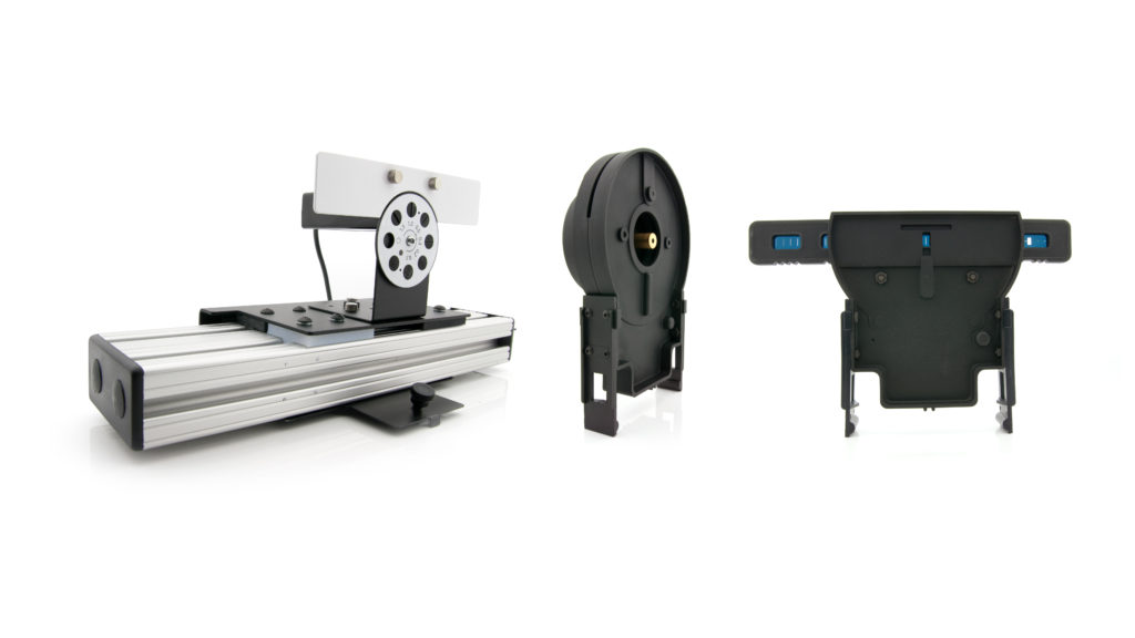
With the Diffraction Apparatus, students measure the intensity as a function of position for various diffraction and interference patterns. The apparatus includes a Red Diffraction Laser (Class 2 laser), a Diffraction Slit System, and a Combination Linear Position and High Sensitivity Light Sensor. A required accessory is the Combination Dynamics Track and Optics Bench (TRACK), which is also available as a part of any of our Dynamics Cart and Track Systems (any of our DTS products). The diffraction components attach to the track. The 1.2 meter track is recommended.
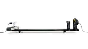
The Combination Linear Position and High Sensitivity Light Sensor has an analog output (BTA) for the light sensor and a digital output (BTD) for the position sensor.
An optional Green Diffraction Laser (GDL-DAK), not included with the basic Diffraction Apparatus, facilitates the study of the impact of light wavelength on diffraction and interference patterns. The Green Diffraction Laser is also a Class 2 laser product.
With all this equipment, students are able to investigate relationships between
- Slit width and pattern spacing
- Double slit separation and pattern spacing
- Intensity as a function of position for single slit diffraction
- Intensity as a function of position for double slit interference
- Effect of light wavelength on all patterns
Note: Vernier products are designed for educational use. Our products are not designed nor are they recommended for any industrial, medical, or commercial process such as life support, patient diagnosis, control of a manufacturing process, or industrial testing of any kind.
What’s Included
- Red Diffraction Laser (635 ±5 nm)
- Diffraction Slit System, with a variety of single slits, double slits, variable slits, and comparison slits
- Combination Linear Position and High Sensitivity Light Sensor
- Power Supply for Laser
Note: The power supply is interchangeable with that used for any LabQuest interface.
Diffraction Apparatus Assembly
The laser and slit are at one end of the track, and the combination light sensor and linear position sensor is positioned at the other. The separation allows the interference pattern to spread sufficiently to facilitate easy measurement of the spacing.
- Place the dynamics track on a level surface. Use of adjustable feet for the track is convenient, but optional.
-
Attach the Combination Linear Position and High Sensitivity Light Sensor to the track with the light sensor facing down the length of the track. It is convenient to place the front edge of the position sensor at about the 110 cm mark. The center tabs on the sensor base rest in the center groove of the track. Slide the light sensor to approximately the center of the position sensor.

- Set the entrance aperture disk of the light sensor to the 0.3 mm setting, and set the light sensor sensitivity to the middle, 10 µW, setting.
- Attach the slit assembly to the track with the label and silver reflective side facing away from the Combination Linear Position and High Sensitivity Light Sensor. A good starting position is at the 20 cm mark on the track. Select the 0.04/0.25 mm double slit.
-
Attach the Red Diffraction Laser to the track, facing the slit assembly. An appropriate starting position is at the 5 cm mark.
- Attach the Power Supply to the laser and to an electrical outlet.
- The rocker switch on the back of the laser turns the laser on when the upper edge is depressed. Turn on the laser and confirm that you see red light striking the slit assembly.
-
Adjust the vertical and horizontal direction of the laser using the two thumbscrews on the back of the laser, so that the beam passes through the double slit and falls on the light sensor front plate. Roughly center the diffraction pattern on the top entrance aperture of the light sensor.
Compatible Software
Choose a platform below to see its compatibility requirements.LabQuest
Interface LabQuest App LabQuest 3 Full support LabQuest 2 Full support LabQuest Full support Computers
Software Interface Graphical Analysis Graphical Analysis (Web App) Logger Pro (discontinued) LabQuest Mini Full support Full support Full support LabQuest 3 Full support Full support Full support LabQuest 2 Full support Full support Full support LabQuest Stream Full support 1 Full support 1 Partial support 2 LabQuest Full support Full support Full support LabPro Incompatible Incompatible Full support Compatibility Notes
Chromebook
Software Interface Graphical Analysis (Web App) LabQuest Mini Full support LabQuest 3 Full support LabQuest 2 Full support LabQuest Stream Full support 1 LabQuest Full support Compatibility Notes
iOS
Software Interface Graphical Analysis Graphical Analysis GW LabQuest Stream Full support Incompatible LabQuest 3 Full support 1 Full support 1 LabQuest 2 Full support 1 Full support 1 Compatibility Notes
Android
Software Interface Graphical Analysis Graphical Analysis GW LabQuest Stream Full support Incompatible LabQuest 3 Full support 1 Full support 1 LabQuest 2 Full support 1 Full support 1 Compatibility Notes
Arduino
Software Interface Arduino Vernier Arduino® Interface Shield Full support 1 2 Compatibility Notes
LabVIEW
Software Interface NI LabVIEW SensorDAQ Full support 1 2 Vernier myDAQ Adapter Full support 1 2 LabQuest Mini Full support 1 LabQuest Stream Full support 1 LabQuest 3 Full support 1 LabQuest 2 Full support 1 LabQuest Full support 1 Compatibility Notes
Getting Started
- Assemble the Diffraction Apparatus by following the steps in the Diffraction Apparatus Assembly section.
- Move the position sensor to the far right as viewed from the light sensor side.
- Connect the sensor to the interface (LabQuest Mini, LabQuest 3, etc.).The Linear Position Sensor cable connects to a digital port and the High Sensitivity Light Sensor cable connects to an analog channel.
- Start the appropriate data-collection software (Vernier Graphical Analysis®, LabQuest® App, or Logger Pro™) if not already running, and choose New from File menu. The software will identify the sensor and load a default data‑collection setup. You are now ready to collect data.
- Grasp the position sensor, and slowly and smoothly move the light sensor across the full width of the stage. Take about 30 seconds to perform the motion. If you move too quickly, the light sensor will not have time to respond to variations in the intensity pattern. You can always test your run by storing it, and immediately taking another run. The new run should lie nearly on top of the first one. Note: For the LabPro only, the zero will drift if the light sensor is moved in between data-collection runs. Re-zero the sensor if needed.
If you are collecting data using a Chromebook™, mobile device such as iPad® or Android™ tablet, or a Vernier wireless interface, please see the following link for up-to-date connection information:
http://www.vernier.com/til/5961
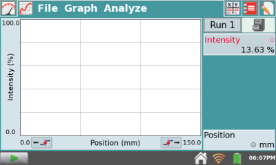
Note: A graph of intensity vs. position displays by default.
Specifications
|
Red laser wavelength |
635 ±5 nm; Class 2 laser product or 520 1 nm; Class 2 laser product |
|
Optional green laser wavelength |
532 ±1 nm; Class 2 laser product |
|
Light sensor full scale ranges |
1, 10, and 100 µW |
|
Linear position sensor range |
150 mm |
|
Linear position sensor resolution |
40 µm |
Note: The optional green laser, depending on its date of manufacture, may be one of the two wavelengths specified. The wavelength is printed on the label on the front of the laser unit.
Laser Safety
- Both the Red Diffraction Laser and Green Diffraction Laser are Class 2 laser products.
- Do not stare directly into the laser beam or its reflection.
- Maximum output is < 1 mW.
A Class 2 laser is generally considered safe as the blink reflex will limit exposure to short time periods. Most laser pointers are in this class. Direct exposure on the eye by a beam of laser light should always be avoided with any laser, no matter how low the power.
How the Linear Position Sensor Works
The Linear Position Sensor is based on an optical encoder. As the position sensor is moved left and right by hand, a strip of narrow alternating black and clear bands pass an optical sensor. The events are counted and turned into a position reading. The resolution is about 40 µm. There is no backlash because the system has only one moving part.
Graphical Analysis, Logger Pro, and LabQuest App will set the position reading to zero when the software is launched or File | New is chosen. To rezero the position sensor, move the position sensor to the far right edge while looking at the light sensor aperture plate.
- On Graphical Analysis, click or tap the Position meter and choose Zero.
- On Logger Pro, click the zero button in the toolbar, select only the position sensor, and click ok.
- On LabQuest App meter screen, tap the Position meter and choose Zero.
How the High Sensitivity Light Sensor Works
The High Sensitivity Light Sensor includes an aperture plate with selectable 0.1, 0.2, 0.3, 0.5, 1.0, and 1.5 mm width entrance slits, as well as full open and full blocked apertures. These slits are used to limit the acceptance of the sensor in the horizontal direction to optimize the spatial resolution of the overall system. The slit choice is a tradeoff between light quantity and spatial resolution. Faint, broad patterns are best studied with wider slits, while bright, highly detailed patterns will require narrower slits. The 0.5 mm slit is a good place to start. If features in the collected data are on the order of 0.5 mm wide, you may want to try narrower slits. Or, try data collection with a narrower slit to see if the pattern shape changes. Typically the modulation of an interference pattern will increase with narrower slits, but the intensity will decrease.
The light sensor itself has three ranges. The nominal full-scale reading corresponds roughly to 1, 10, or 100 µW, as selected. The sensor responds throughout visible wavelengths. However, each range is reported in percent of full scale, or 0 to 100%, as absolute calibration is not relevant to these experiments. It is normal for the sensor to read between 10 and 20% when the sensor is in the dark. Optionally, the light sensor can be zeroed. To do this, rotate the aperture plate to the blank (black circle) position to block all light from the sensor.
- On Graphical Analysis, click or tap the Light meter and choose Zero.
- On LabQuest App meter screen, tap the light meter and choose zero.
- On Logger Pro, click the zero button in the toolbar, select only the light sensor, and click ok.
The light sensor is not designed to be removed from the Linear Position Sensor.
Slit Assembly
The slits are made of metal-on-glass films, and so present very clean diffraction and interference patterns.
Available Slits
|
Single slits |
0.02, 0.04, 0.08, 0.16 mm width |
|
Double slits |
0.04 / 0.25, 0.04 / 0.5, 0.08 / 0.25, 0.08 / 0.5 mm width and separation |
|
Variable slits |
Single slit: 0.02–0.2 mm width Double slit: 0.04 mm width, |
|
Multiple slits |
0.04 mm width, 0.125 mm spacing: 2, 3, 4, 5 slits |
|
Comparisons |
4 pairs of single/double slits: 0.04 mm single + 0.04/0.25 mm double, doubles 0.04/0.25 +0.04/0.50, doubles 0.04/0.25+0.08/0.25, double 0.04/0.25 + triple, 0.04/0.25 |
|
Other shapes |
Slit and line comparison 0.08 mm slit and opaque line on clear background; 0.20mm and 0.40 mm round holes |
Slit Applications
- The single slits, double slits, and multiple slit patterns are designed for quantitative experiment.
- The variable slits cast vertical patterns to be shown on a white surface and are intended for qualitative viewing. You may choose to use the screen included with the Vernier Optics Expansion Kit (order code OEK), or available separately as a replacement part (order code SCRN-OEK).
- The comparison slits are used by adjusting the laser up and down to compare patterns visually and qualitatively; because the beam won’t be fully horizontal, the pattern may not strike the light sensor.
- The slit and line comparison is intended to be used qualitatively, to observe the pattern similarity between that of a single slit and a single opaque line.
- The circular apertures are intended for qualitative viewing of the diffraction pattern from a hole, as opposed to a line.
Troubleshooting
For troubleshooting and FAQs, see www.vernier.com/til/2995
Sample Experiments with the Diffraction Apparatus
The variety of slits provided with the Diffraction Apparatus suggests many experiments. In most cases each activity can be done to two depths: the spacing of the dark or light bands can be measured and compared to calculation, or the quantitative shape of the patterns can be compared to calculation.
Detents in the slider assembly hold the selected slit in position during an experiment. The variable slit choices have no detent to allow smoothly changing the slit position.
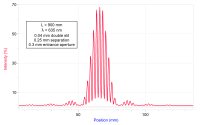
Sample graph of double slit diffraction pattern, with two 0.04 mm slits 0.25 mm apart
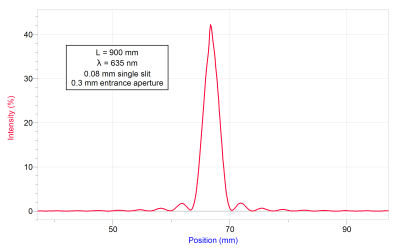
Sample graph of single slit interference pattern, with one 0.08 mm slit
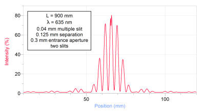
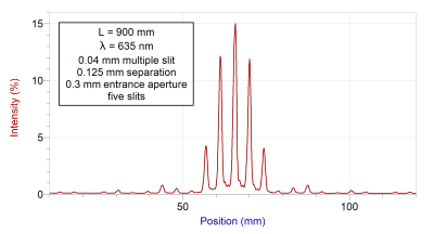
Sample graphs of multiple slit diffraction pattern, with 0.04 mm slits at a 0.125 mm separation, 2 and 5 slits
The remaining slits are intended for viewing by eye and not necessarily doing measurements with the light sensor and position stage.
The slit assembly includes a variable width single slit and a variable separation double slit. To demonstrate the effect of smoothly changing either variable, start with the laser striking roughly in the middle of the pattern, and slide the slit assembly right or left.
Comparison with Theory
Experiments with the Diffraction Apparatus are typically done either as a full model of the intensity distribution of the patterns or as a simpler search for the locations of bright and dark fringes. The basic models are provided here. Note: This is adapted from Fundamentals of Physics, 9th edition, Halliday and Resnick, Wiley, 2011.
Intensity Distribution
Double-slit interference intensity as a function of angle for slits of width a and separation d is given by

where
Im is the maximum intensity, and is an overall scale factor. λ is the light wavelength.
Single-slit diffraction for a slit of width a is given by

For comparison with data from the Diffraction Apparatus, you will need to apply the small angle approximation. Using a distance L from the slit to the screen (or entrance aperture) along the track, and a position y along the line perpendicular to the track, we have
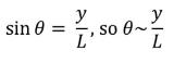
since y << L.
In practice the location of the origin of y axis will vary by a small amount depending on exactly how the laser is directed. The zero of the position sensor will be very different from the origin location on y.
Occasional differences from theory may occur due to reflections from the glass slits. The reflection may cause the central peak to have a dip or spike in magnitude from expectations. The dip will be very close to the center of the pattern, but may be offset to one side slightly. This is normal.
To compare experimental data with model, adjust the overall scale of the model to match the data, and add a horizontal offset to bring the model in line with the experimental data, which will not be centered on zero.
Fringe Location Only
The locations of the dark fringes in a single slit are give by

For a double slit, the bright fringe locations are given by

In short, the distance from one dark fringe to the next in single slit diffraction is λL/a, and the distance from one bright fringe to the next in double slit interference is λL/d.
Repair Information
If you are having trouble with your Diffraction Apparatus, contact Vernier Technical Support at physics@vernier.com or call 888-837-6437. Support specialists will work with you to determine if the unit needs to be sent in for repair. At that time, a Return Merchandise Authorization (RMA) number will be issued and instructions will be communicated on how to return the unit for repair.
Accessories/Replacements
| Item | Order Code |
|
TRACK |
|
|
DTS |
|
|
GDL-DAK |
|
|
SCRN-OEK |
|
|
OEK |
Warranty
Warranty information for this product can be found on the Support tab at www.vernier.com/dak/#support
General warranty information can be found at www.vernier.com/warranty
Contact Support
Fill out our online support form or call us toll-free at 1-888-837-6437.