Magnetic Field Sensor User Manual
Order Code: MG-BTA
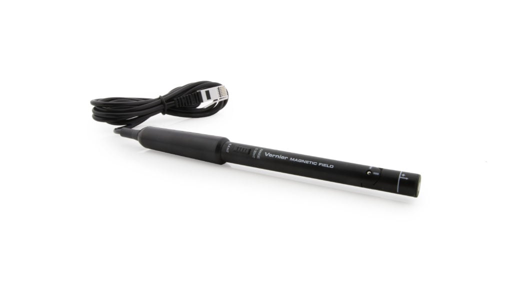
The Vernier Magnetic Field Sensor measures a vector component of the magnetic field near the sensor tip. The tip can be adjusted, allowing the user to measure fields that are parallel or perpendicular to the long axis of the sensor. The Magnetic Field Sensor can be used for a variety of interesting experiments involving magnetic fields.
- Measure and study the Earth’s magnetic field.
- Determine the direction of magnetic north.
- Study the magnetic field near a permanent magnet.
- Measure the field near a current-carrying wire.
- Measure the field at the opening of a solenoid.
Note: Vernier products are designed for educational use. Our products are not designed nor are they recommended for any industrial, medical, or commercial process such as life support, patient diagnosis, control of a manufacturing process, or industrial testing of any kind.
Compatible Software and Interfaces
Choose a platform below to see its compatibility requirements.LabQuest
Interface LabQuest App LabQuest 3 Full support LabQuest 2 Full support LabQuest Full support Computers
Software Interface Graphical Analysis Graphical Analysis (Web App) Logger Pro (discontinued) Logger Lite (discontinued) LabQuest Mini Full support Full support Full support Full support LabQuest 3 Full support Full support Full support Incompatible LabQuest 2 Full support Full support Full support Full support LabQuest Stream Full support 1 Full support 1 Partial support 2 Full support 1 Go!Link Full support Full support Full support Full support LabQuest Full support Full support Full support Full support LabPro Incompatible Incompatible Full support Full support Compatibility Notes
Chromebook
Software Interface Graphical Analysis (Web App) LabQuest Mini Full support LabQuest 3 Full support LabQuest 2 Full support LabQuest Stream Full support 1 Go!Link Full support LabQuest Full support Compatibility Notes
iOS
Software Interface Graphical Analysis Graphical Analysis GW LabQuest Stream Full support Full support LabQuest 3 Full support 1 Full support 1 LabQuest 2 Full support 1 Full support 1 Compatibility Notes
Android
Software Interface Graphical Analysis Graphical Analysis GW LabQuest Stream Full support Full support LabQuest 3 Full support 1 Full support 1 LabQuest 2 Full support 1 Full support 1 Compatibility Notes
Arduino
Software Interface Arduino Vernier Arduino® Interface Shield Full support LabVIEW
Software Interface NI LabVIEW SensorDAQ Full support Vernier myDAQ Adapter Full support 1 Go!Link Full support LabQuest Mini Full support LabQuest Stream Full support LabQuest 3 Full support LabQuest 2 Full support LabQuest Full support Compatibility Notes
Texas Instruments
Software Interface EasyData DataMate TI-84 SmartView DataQuest TI-Nspire Software EasyLink Full support 1 Incompatible Full support 2 Full support Full support 2 CBL 2 Full support 3 Full support 3 4 Incompatible Incompatible Incompatible LabPro Full support 3 Full support 3 4 Incompatible Incompatible Incompatible TI-Nspire Lab Cradle Incompatible Incompatible Incompatible Full support Full support Compatibility Notes
Quick Start
- Plug the sensor into the interface (LabQuest 3, LabQuest Mini, etc.).
- Connect the interface to your device.
- If using USB, connect to the USB port on your computer.
- If using Bluetooth® wireless technology, click your interface type and then select your device.
- Prepare for data collection:
- Vernier Graphical Analysis®: Launch the app, if necessary, and click Sensor Data Collection.
- LabQuest® App: Choose New from the File menu.
The software will identify the sensor and load a default data-collection setup. You are now ready to collect data.
Need Additional Information?
Visit the following link:
Using the Sensor
Connect the sensor following the steps in the Quick Start section of this user manual.
Use the switch on the sensor shaft to select an appropriate range.
- The 6.4 mT range is used to measure relatively strong magnetic fields around permanent magnets and electromagnets.
- The 0.32 mT range is used mainly to measure the magnetic field of the Earth and very weak fields. It can be used for other magnets, but the sensor must remain in one position so that the reading is not affected by the background field of the Earth.
Videos
Calibration
You should not have to perform a new calibration when using the Magnetic Field Sensor. We have set the sensor to match our stored calibration before shipping it.
It is not practical to calibrate the Magnetic Field Sensor without reference to a known source of magnetic field. It is useful, however, to zero the Magnetic Field Sensor. Position the sensor and zero it using your data-collection software. Move the magnetic field source, and not the sensor, to explore the spatial variations of the field.
Moving the sensor will upset the zero since the background magnetic field in your lab probably varies with position. For experiments measuring the spatial variation of a magnetic field, it is better to zero the sensor and then move the source to various positions.
Specifications
|
Sensor location |
~1 cm from the wand tip with the white dot as indicated by the white line on newer sensors |
|
Resolution |
|
|
Stored calibration value |
|
|
Stored calibration value |
|
|
Stored calibration value |
|
|
Stored calibration value |
|
How the Sensor Works
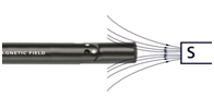
The sensor uses a Hall-effect transducer. It produces a voltage that is linear with magnetic field. The sensor measures the component of the magnetic field that is perpendicular to the white dot on the end of the sensor tip. The reading is positive when the white dot on the sensor points toward a magnetic south pole.
The switch on the sensor shaft is used to select the range. On the 6.4 mT range, each volt measured by the transducer represents 32 gauss (3.2 × 10⁻³ tesla). The range of the sensor is ±64 gauss or ±6.4 × 10⁻³ tesla. On the 0.3 mT range, each volt measured represents 1.6 gauss (1.6 × 10⁻⁴ tesla). The range of the sensor is ±3.2 gauss or ±3.2 × 10⁻⁴ tesla.
If the sensor tube is held vertically with the tip horizontal, and rotated until the maximum voltage is found, the tip with the white dot will point to magnetic north. The magnetic inclination in your area can be found by holding the tube so that the white dot is facing north, and rotating the sensor end of the tube down until the voltage reaches a maximum. The angle of the tip from the vertical position is the magnetic inclination. Note that the north pole of a freely suspended magnet points north, since the magnetic pole of the Earth in the northern hemisphere is a south magnetic pole.
Troubleshooting
If you are getting unexpected or unusual readings from the Magnetic Field Sensor, first confirm that the range setting is appropriate for the experiment. The ±6.4 mT range is used to measure relatively strong magnetic fields around permanent magnets and electromagnets; the ±0.32 mT range is used to measure the magnetic field of the Earth and very weak fields. If you are using the ±0.32 mT range for investigating permanent magnets, make sure that the sensor remains in one position so that the reading is not affected by the background field of the Earth.
For other troubleshooting tips and FAQs, see www.vernier.com/til/1420
Repair Information
If you have watched the related product video(s), followed the troubleshooting steps, and are still having trouble with your Magnetic Field Sensor, contact Vernier Technical Support at support@vernier.com or call 888-837-6437. Support specialists will work with you to determine if the unit needs to be sent in for repair. At that time, a Return Merchandise Authorization (RMA) number will be issued and instructions will be communicated on how to return the unit for repair.
Warranty
Warranty information for this product can be found on the Support tab at www.vernier.com/mg-bta/#support
General warranty information can be found at www.vernier.com/warranty
Contact Support
Fill out our online support form or call us toll-free at 1-888-837-6437.