Photogate User Manual
Order Code: VPG-BTD
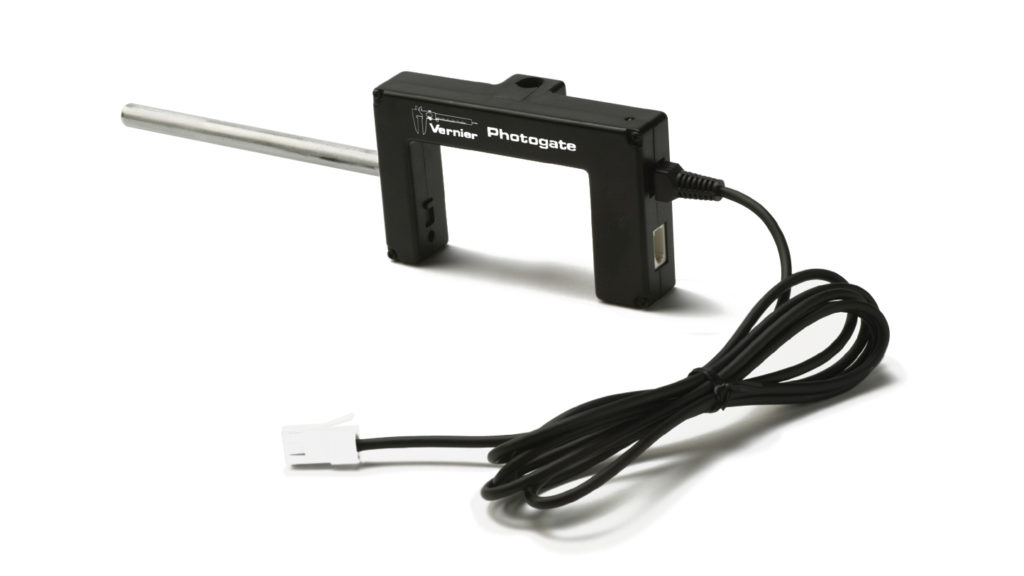
The Vernier Photogate is used for speed and acceleration measurements of objects passing through the gate. The object blocks an infrared beam as it passes. Motion data can be determined in software from the timing of beam blocking.
This general-purpose photogate can be used for a wide variety of experiments in physics and physical science classes. Examples include
- measuring freefall acceleration
- studying the swing of a pendulum
- measuring the speed of a rolling object
- timing the period of a rotating object
- measuring the speed of objects undergoing collisions
The Vernier Photogate can be used as a traditional photogate for objects traveling between the arms of the gate, and also as a laser gate for objects passing outside of the arms of the gate. A mechanical shutter is used to block the internal gate, switching the device to laser gate mode. The laser gate mode requires a visible pen laser (LASER, included). You can expect good results with a typical Class IIIa type laser pointer with a power of less than 5 mW.
The Vernier Photogate can be connected directly to an interface or in a daisy‑chain configuration. In the daisy‑chain mode, up to four photogates can be connected to a single channel of the interface by connecting one photogate to another photogate, connecting the last one directly to the interface.
Note: Vernier products are designed for educational use. Our products are not designed nor are they recommended for any industrial, medical, or commercial process such as life support, patient diagnosis, control of a manufacturing process, or industrial testing of any kind.
What's Included
- Photogate
- Photogate Cable
- Accessory Rod
Compatible Software and Interfaces
Choose a platform below to see its compatibility requirements.LabQuest
Interface LabQuest App LabQuest 3 Full support LabQuest 2 Full support LabQuest Full support Computers
Software Interface Graphical Analysis Graphical Analysis (Web App) Logger Pro (discontinued) LabQuest Mini Full support Full support Full support LabQuest 3 Full support Full support Full support LabQuest 2 Full support Full support Full support LabQuest Stream Full support 1 Full support 1 Partial support 2 LabQuest Full support Full support Full support LabPro Incompatible Incompatible Full support Compatibility Notes
Chromebook
Software Interface Graphical Analysis (Web App) LabQuest Mini Full support LabQuest 3 Full support LabQuest 2 Full support LabQuest Stream Full support 1 LabQuest Full support Compatibility Notes
iOS
Software Interface Graphical Analysis Graphical Analysis GW LabQuest Stream Full support Incompatible LabQuest 3 Full support 1 Full support 1 LabQuest 2 Full support 1 Full support 1 Compatibility Notes
Android
Software Interface Graphical Analysis Graphical Analysis GW LabQuest Stream Full support Incompatible LabQuest 3 Full support 1 Full support 1 LabQuest 2 Full support 1 Full support 1 Compatibility Notes
Arduino
Software Interface Arduino Vernier Arduino® Interface Shield Full support LabVIEW
Software Interface NI LabVIEW SensorDAQ Full support Vernier myDAQ Adapter Full support LabQuest Mini Full support LabQuest Stream Full support LabQuest 3 Full support LabQuest 2 Full support LabQuest Full support Texas Instruments
Software Interface EasyData DataMate DataQuest TI-Nspire Software CBL 2 Full support 1 Full support 1 2 3 Incompatible Incompatible LabPro Full support 1 Full support 1 2 3 Incompatible Incompatible TI-Nspire Lab Cradle Incompatible Incompatible Full support Full support Compatibility Notes
Assembly
Mounting the Photogate
Connect the clear phone plug from the cable assembly into the modular phone jack on the Photogate housing. Plug the other end of the cable assembly into the lab interface or adapter cable. Test the operation of the Photogate by watching the LED when the beam is blocked. The LED will go on when the Photogate is blocked. The rod included with the Photogate can be threaded into the hole in the Photogate end to provide a convenient way of mounting the Photogate. The rod can be clamped to a ring stand or support rod using standard laboratory right-angle clamps. For internal gate mode, position the Photogate so the object to be timed will pass through the Photogate arms, blocking the beam. For external laser gate mode, it is easier to roughly align the laser, and then position the Photogate so the LED goes out.
Add a Low-Friction Pulley
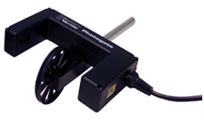
The Ultra Pulley Accessory (order code SPA, not included) connects to the Photogate by using the accessory rod that comes with the Photogate. Place the rod through the hole in the Photogate and move the pulley into position so that the rod can be threaded into it. Tighten up the rod so that the pulley is held firmly against the Photogate. The Ultra Pulley is a low-friction pulley with ten spokes. The spokes break the Photogate beam so that the rotation of the pulley can be monitored by the Photogate. For example, the motion of an Atwood’s machine could be studied with an Ultra Pulley and the Vernier Photogate.
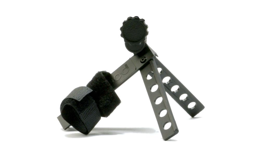
Laser Pointer Stand
This light weight stand (order code STAND, not included) is a perfect support for a laser pointer. The stand features clips attached to the height adjustable pivoting bracket. This assembly allows you to accurately point the laser at the Photogate.
Getting Started
- Connect the sensor to the interface (LabQuest Mini, LabQuest 3, etc.).
- Start the appropriate data-collection software (Vernier Graphical Analysis®, LabQuest®, or Logger Pro™) if not already running, and choose New from File menu.
The software will identify the sensor and load a default data-collection setup for a picket fence free-fall experiment. To configure other experiments and timing modes, see www.vernier.com/til/1422
If you are collecting data using a Chromebook™, mobile device such as iPad® or Android™ tablet, or a Vernier wireless sensor or interface, please see the following link for up-to-date connection information:
Using the Product
Connect the sensor following the steps in the Getting Started section of this user manual.
Internal Gate Mode and Laser Gate Mode
The Vernier Photogate operates in two modes. A shutter over the internal gate detector determines the operating mode. The shutter is on the inside of the thinner gate arm. Open the shutter to use the internal gate, and close the shutter to use the external laser gate. A red LED is on when the gate is blocked in either mode.
To use the internal gate mode, open the shutter and position the Photogate. When the gate is blocked the red LED will be illuminated.
To use the external laser gate mode, close the shutter for the internal gate. The laser port is on the outside edge of the gate adjacent to the captive bolt. Align your laser so the beam enters the port and turns off the LED. Blocking the laser beam at any point in its path will then turn the LED back on. The path of the laser need not be a straight line. You may want to use mirrors to create a complex path that is crossed by the moving object multiple times.
Laser Safety Note: Do not align the external laser gate by sighting by eye. Follow all safety precautions indicated by the laser manufacturer.
Daisy-Chain Mode
The Vernier Photogate can be connected in a daisy-chain mode. Connect one gate to the interface, and then connect the next gate to the first Photogate using the white BTD socket on the arm of the Photogate. Up to four Vernier Photogates can be connected to an interface at one time. The daisy-chain mode requires the cable from the VPG‑BTD model. If you have the VPG-DG version, you will need to purchase an additional cable to make each photogate-to-photogate connection (order code PG‑BTD).
In the daisy-chain mode, the analyzing software has no way to determine which gate has been blocked, so be sure that this information is not needed. One common setup is to use gate timing, so that the software reports the time a gate is blocked. If you know the order in which gates are blocked from the geometry of the experiment, then daisy-chain mode will work.
Note that in a typical collision experiment with two objects passing through the two gates, the gates may have overlapping block intervals. In this case, you must connect the gates to two separate channels on the interface. Motion timing mode can be used if the daisy-chained gates are equally spaced. Enter the distance between gates in your software to determine position, velocity, and acceleration of a single object passing through a series of photogates.
This sensor is equipped with circuitry that supports auto-ID. When used with LabQuest 3, LabQuest 2, original LabQuest, LabQuest Mini, LabPro, SensorDAQ, TI-Nspire Lab Cradle, or CBL 2, the data-collection software identifies the sensor and uses pre-defined parameters to configure an experiment appropriate to the recognized sensor.

More Information on Geometric Aspects of Photogate Timing
Photogates have geometric complications that result in the effective length of an object passing through the gate being slightly less than the actual length.
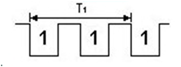
Motion Timing (Linear Motion and Angular Motion)
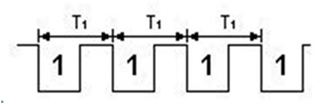
The Motion Timing mode uses a photogate or pulley connected to the digital input. During operation, times are recorded as leading opaque edges of a “picket fence,” bar tape, or a pulley spoke pass through the photogate beam. These times are displayed in a data table. More importantly, if you enter the distance between the leading edges of the opaque bands, the program can analyze the times and calculate displacements, velocities, and accelerations.
Pulse Timing (Time Between Gates and Speed through Gate using Gate Separation)
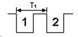
In this mode, a measurement from when a photogate gets blocked to when it gets blocked again will be recorded. If the distance the object travels between blocked times is entered,
the average velocity of the object is calculated.
Gate Timing (Speed through Gate using Flag Width)
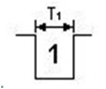
For this mode, timing begins when the photogate is first blocked. The timing continues until the gate is unblocked. The duration of the interruption is thus timed. If the length of the object (flag width) is entered, the velocity is calculated.
Pendulum Timing (Pendulum Period)
Pendulum Timing mode uses a photogate connected to an interface. The timing begins when the photogate is first interrupted. The timing continues until the photogate is interrupted twice more, so that you get the time for a complete swing of a pendulum or other oscillating object.
Photogate Timing
In Photogate Timing mode, only a time and Gate State column are displayed. You may add other calculated columns as desired.
For a good discussion of these issues, see “Photogates: An instrument evaluation,” Eugene P. Mosca and John P. Ertel, Am. J. Phys. 57 (9), 840–844 (1989).
A more comprehensive tutorial can be found in the following documents:
- Logger Pro Introduction to the Vernier Photogate
- LabQuest Introduction to the Vernier Photogate
Experiments Using the Vernier Photogate
The Vernier Photogate is used in several experiments in the book Physics with Vernier. See this book for detailed experiments. Here are some brief examples of things you can do with a photogate.
- If you have a Picket Fence, you can determine the acceleration due to the gravity of an object in free fall. This is the default experiment for most photogate software and is described in detail in out Photogate Tech Tips video.
- Using two photogates positioned at a known separation, you can determine the speed of an object from the time interval between the breaking of the first beam to the breaking of the second. This mode is known as pulse timing.
- Set up a pendulum so that the bob swings through the photogate. The time interval from one block to the third block yields the pendulum period.
- Use the laser gate at floor level to measure the “hang time” of a jumper. The jumper’s shoes will block the beam while on the floor. The time interval of interest is then the unblock to block time.
- Use an Ultra Pulley Attachment to construct an Atwood’s machine, consisting of two masses connected by a flexible string. The string passes over the pulley, causing it to rotate as the masses move. Use motion timing to measure the position, velocity, and acceleration as a function of time.
- Measure the free fall acceleration of a picket fence using either the internal gate or the laser gate. Motion timing will give you the position, velocity, and acceleration as a function of time. Do the two modes give different results?
Videos
Calibration
The Vernier Photogate does not require calibration.
Specifications
|
Power requirements |
5 VDC at 40 mA |
|
Infrared source |
Peak at 880 nm |
|
Dimension |
75 mm gate width |
|
Resolution |
1 μs |
|
Output is high and LED off for unblocked gate |
|
|
Output is low and LED on for blocked gate |
|
|
Beam approximately 9 mm from the end of the gate arms |
|
How Sensor Works
The sensor has an infrared LED emitter on one arm and a phototransistor on the other arm. An object blocks the infrared beam as it passes. Motion data can be determined in software from the timing of beam blocking.
Troubleshooting
- The Photogate arms have a sliding shutter to block the internal beam. This configuration is needed when using the external laser gate. If the desired use is the internal gate, but the shutter is closed, the Photogate will always read blocked. Open the shutter to use the internal gate.
- The Photogate requires the selection of a data-collection mode. See the following articles for more detailed information:
- For Graphical Analysis and Graphical Analysis Pro, see www.vernier.com/til/4313/
- For LabQuest App, see www.vernier.com/til/3329/
- For Logger Pro, see www.vernier.com/til/3328/
- It is normal for data tables from photogate experiments to be sparse. See www.vernier.com/til/2698/ for more information.
- For additional troubleshooting and FAQs, see www.vernier.com/til/1422/
Repair Information
If you have watched the related product video(s), followed the troubleshooting steps, and are still having trouble with your Vernier Photogate, contact Vernier Technical Support at support@vernier.com or call 888-837-6437. Support specialists will work with you to determine if the unit needs to be sent in for repair. At that time, a Return Merchandise Authorization (RMA) number will be issued and instructions will be communicated on how to return the unit for repair.
Accessories/Replacements
| Item | Order Code |
|---|---|
|
PF |
|
|
PF-CART |
|
|
SPA |
|
|
B-SPA |
|
|
TAPE-VPG |
|
|
TAPE |
|
|
LASER |
|
|
STAND |
Warranty
Warranty information for this product can be found on the Support tab at www.vernier.com/vpg-btd/#support
General warranty information can be found at www.vernier.com/warranty
Contact Support
Fill out our online support form or call us toll-free at 1-888-837-6437.