3-Axis Accelerometer User Manual
Order Code: 3D-BTA
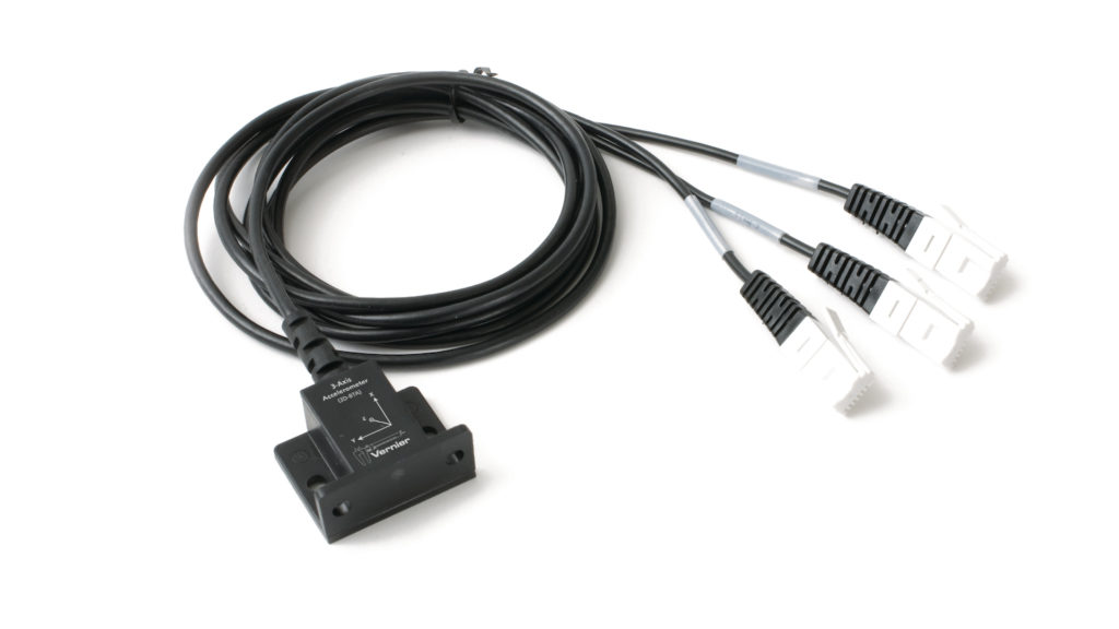
The 3-Axis Accelerometer consists of three –5g to +5g accelerometers mounted in one small block. Using the appropriate data‑collection hardware and software, you can graph any of these components, or calculate the magnitude of the net acceleration. The 3-Axis Accelerometer can be used for a wide variety of experiments and demonstrations, both inside and outside the lab.
Note: Vernier products are designed for educational use. Our products are not designed nor are they recommended for any industrial, medical, or commercial process such as life support, patient diagnosis, control of a manufacturing process, or industrial testing of any kind.
Compatible Software and Interfaces
Choose a platform below to see its compatibility requirements.LabQuest
Interface LabQuest App LabQuest 3 Full support LabQuest 2 Full support LabQuest Full support Computers
Software Interface Graphical Analysis Graphical Analysis (Web App) Logger Pro (discontinued) Logger Lite (discontinued) LabQuest Mini Full support Full support Full support Full support LabQuest 3 Full support Full support Full support Incompatible LabQuest 2 Full support Full support Full support Full support LabQuest Stream Full support 1 Full support 1 Partial support 2 Full support 1 Go!Link Partial support 3 Partial support 3 Partial support 3 Partial support 3 LabQuest Full support Full support Full support Full support LabPro Incompatible Incompatible Full support Full support Compatibility Notes
Chromebook
Software Interface Graphical Analysis (Web App) LabQuest Mini Full support LabQuest 3 Full support LabQuest 2 Full support LabQuest Stream Full support 1 Go!Link Partial support 2 LabQuest Full support Compatibility Notes
iOS
Software Interface Graphical Analysis Graphical Analysis GW LabQuest Stream Full support Full support LabQuest 3 Full support 1 Full support 1 LabQuest 2 Full support 1 Full support 1 Compatibility Notes
Android
Software Interface Graphical Analysis Graphical Analysis GW LabQuest Stream Full support Full support LabQuest 3 Full support 1 Full support 1 LabQuest 2 Full support 1 Full support 1 Compatibility Notes
Arduino
Software Interface Arduino Vernier Arduino® Interface Shield Partial support 1 Compatibility Notes
LabVIEW
Software Interface NI LabVIEW SensorDAQ Full support Vernier myDAQ Adapter Partial support 1 2 Go!Link Partial support 3 LabQuest Mini Full support LabQuest Stream Full support LabQuest 3 Full support LabQuest 2 Full support LabQuest Full support Compatibility Notes
Texas Instruments
Software Interface EasyData DataMate TI-84 SmartView DataQuest TI-Nspire Software EasyLink Partial support 1 2 Incompatible Partial support 1 3 Partial support 1 Partial support 1 3 CBL 2 Full support 4 Full support 4 5 Incompatible Incompatible Incompatible LabPro Full support 4 Full support 4 5 Incompatible Incompatible Incompatible TI-Nspire Lab Cradle Incompatible Incompatible Incompatible Full support Full support Compatibility Notes
Quick Start
- Plug the sensor into the interface (LabQuest 3, LabQuest Mini, etc.).
- Connect the interface to your device.
- If using USB, connect to the USB port on your computer.
- If using Bluetooth® wireless technology, click your interface type and then select your device.
- Prepare for data collection:
- Vernier Graphical Analysis®: Launch the app, if necessary, and click Sensor Data Collection.
- LabQuest® App: Choose New from the File menu.
The software will identify the sensor and load a default data-collection setup. You are now ready to collect data.
Need Additional Information?
Visit the following link:
www.vernier.com/start-lq-sensor
Note: Vernier products are for educational use only.
Calibration
You should not need to calibrate this sensor. Each sensor is calibrated prior to being shipped to you. In most experiments you can simply use the default calibration, then use the software’s zeroing option to zero the sensor along the axes.
Calibration may be done using the acceleration due to gravity. To calibrate the sensor for measuring acceleration in the horizontal direction:
- Position the accelerometer with the arrow pointing down for the first calibration point.
- Define this as –9.8 m/s2 or –1g.
- Rotate the accelerometer so the arrow points up and use the reading for the second calibration point.
- Define this as +9.8 m/s2 or +1g. The accelerometer will then read 0 with no acceleration when held horizontally.
- Repeat this procedure for each axis.
If you want to calibrate for measuring acceleration in the vertical direction, follow the procedure above, but define the first calibration point as 0g or 0 m/s2 and the second point as 2g or 19.6 m/s2. Note: The two calibrations are not really that different, in both cases there is a 19.6 m/s2 difference in acceleration between the two calibration points.
Specifications
|
Power |
30 mA @ 5 VDC |
|
For each axis |
|
|
Stored calibration information |
|
How the Sensor Works
Since the accelerometer is sensitive to both acceleration and the Earth’s gravitational field, interpreting accelerometer measurements is complex. A useful model for understanding accelerometer measurements is a spring-based scale with a reference mass (or object) attached to the scale. If the scale is pointing upward (the usual orientation for such a device) the weight of the mass causes the spring to compress, and you get a non-zero reading. If you were to turn the scale upside down, the spring will be extended, instead of compressed, and we get a reading of the opposite sign. If you turn the scale so it points sideways, and keep it motionless, then the spring will just be at its relaxed length, and the reading will be zero. If you accelerated the scale toward the mass, then the spring would compress; away, and the spring would stretch.
In each case the scale is reading a value corresponding to the normal force on the mass. This reading can be made relative by dividing out the mass, giving units of N/kg, which is the same as m/s2. Accelerometer measurements can be interpreted in exactly this way.
The 3-Axis Accelerometer contains three acceleration-sensing integrated circuits (ICs), along with the associated electronics. It is functionally equivalent to three of our Low-g Accelerometers (order code LGA-BTA) mounted in a small block at orthogonal angles. Each of the accelerometers measures acceleration along one line and produces a signal on one of the three outputs. These three axes and three outputs are labeled X, Y, and Z. The IC sensors are similar to those originally designed to control the release of air bags in an automobile. This IC is micro-machined with very thin “fingers” carved in silicon. These fingers flex when accelerated. They are arranged and connected like the plates of a capacitor. As the fingers flex, the capacitance changes, and a circuit included in the IC monitors the capacitance, converting it into a voltage. An op-amp circuit amplifies and filters the signal from the IC. The net result is that the voltage varies in a linear way with acceleration.
Each of the outputs is labeled with X, Y, or Z. This corresponds with the directions shown on the label on the sensor. Accelerations are normally measured in either meters per second per second (m/s2) or g. One g is the acceleration due to gravity at the Earth’s surface, or 9.8 m/s2. This accelerometer will measure accelerations in the range of –5g (–49 m/s2) to +5g (+49 m/s2) in each direction.
This is a range of accelerations that a human body could experience without damage. Many collisions will produce much larger accelerations. In fact, dropping the accelerometer on a hard surface from even a few centimeters can produce accelerations of 100g. The 3-Axis Accelerometer will not be damaged by accelerations up to 1000g.
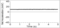
When properly calibrated, when the arrow representing an axis points upward, that channel reads +9.8 m/s2. When an axis arrow points down, that channel should read –9.8 m/s2. When an axis arrow is held horizontally, that channel will read zero. In most cases, data-collection software can be used to create a new column to calculate the square root of the sum of the squares of the accelerations. It will be equal to 9.8 m/s2 when the 3-Axis Accelerometer has no acceleration and zero when it is in free fall. The orientation of the 3-Axis Accelerometer does not matter. To understand how this works, try holding the 3-Axis Accelerometer in your hand and very slowly rotate it about all three axes. The graphs below show the result. The graphs have all three components of acceleration and the net acceleration (the square root of the sum of the squares of the accelerations). Notice that it stays near 9.8 m/s2 throughout all of this rotation.

|
|
The 3-Axis Accelerometer is designed to measure small accelerations with minimal electronic noise. The noise is typically on the order of 0.5 m/s2 peak to peak. The offset voltage (voltage output at 0 m/s2) will drift somewhat with temperature.
Using the 3-Axis Accelerometer as a Single Axis Accelerometer
Since the 3-Axis Accelerometer is equivalent to three Low-g Accelerometers, you can use just one channel of it to study acceleration along a single axis. Mount the accelerometer so that a particular axis is in the direction of interest and monitor just that channel. If the motion is linear, it will keep the analysis simple.
Troubleshooting
For additional troubleshooting and FAQs, see www.vernier.com/til/1412
Repair Information
If you have followed the troubleshooting steps and are still having trouble with your 3-Axis Accelerometer, contact Vernier Technical Support at support@vernier.com or call 888-837-6437. Support specialists will work with you to determine if the unit needs to be sent in for repair. At that time, a Return Merchandise Authorization (RMA) number will be issued and instructions will be communicated on how to return the unit for repair.
Warranty
Warranty information for this product can be found on the Support tab at www.vernier.com/3d-bta/#support
General warranty information can be found at www.vernier.com/warranty
Contact Support
Fill out our online support form or call us toll-free at 1-888-837-6437.