Current Probe User Manual
Order Code: DCP-BTA
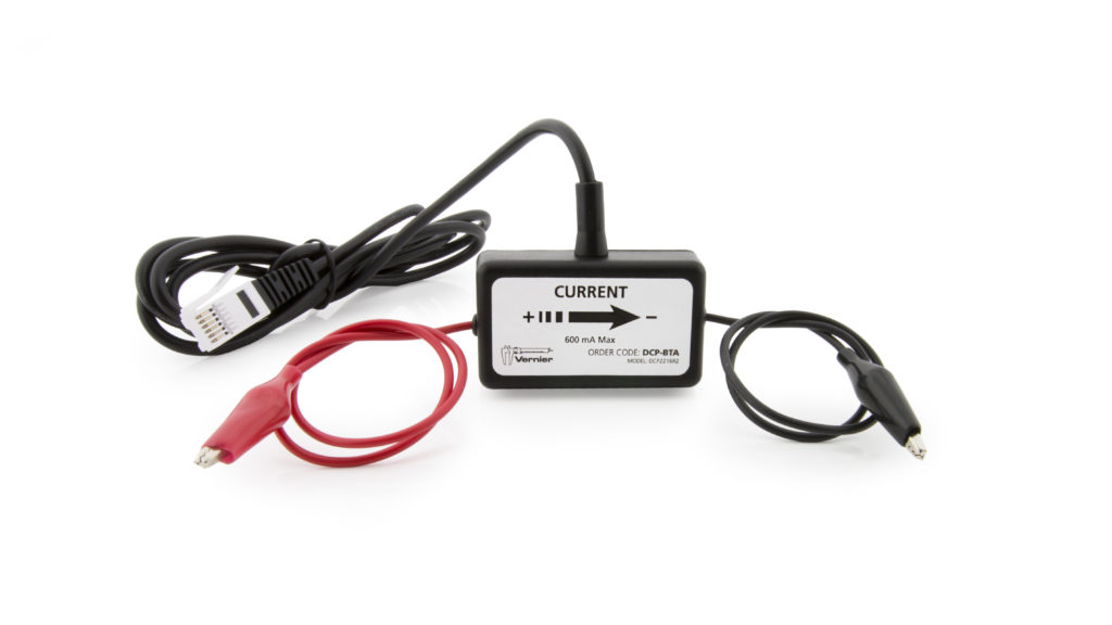
The Current Probe is designed for exploring the basic principles of electricity. The intentional placement of the leads (coming from opposite sides of the sensor) is intended to reinforce the desired series connection of the sensor within a circuit. Use the Current Probe to measure currents in low voltage AC and DC circuits. With a range of ±0.6 A, this sensor is ideal for use in most “battery and bulb” circuits.
Note: Vernier products are designed for educational use. Our products are not designed nor recommended for any industrial, medical, or commercial process such as life support, patient diagnosis, control of a manufacturing process, or industrial testing of any kind.
Compatible Software
Choose a platform below to see its compatibility requirements.LabQuest
Interface LabQuest App LabQuest 3 Full support LabQuest 2 Full support LabQuest Full support Computers
Software Interface Graphical Analysis Graphical Analysis (Web App) Logger Pro (discontinued) Logger Lite (discontinued) LabQuest Mini Full support Full support Full support Full support LabQuest 3 Full support Full support Full support Incompatible LabQuest 2 Full support Full support Full support Full support LabQuest Stream Full support 1 Full support 1 Partial support 2 Full support 1 Go! Link Full support Full support Full support Full support LabQuest Full support Full support Full support Full support LabPro Incompatible Incompatible Full support Full support Compatibility Notes
Chromebook
Software Interface Graphical Analysis (Web App) LabQuest Mini Full support LabQuest 3 Full support LabQuest 2 Full support LabQuest Stream Full support 1 Go! Link Full support LabQuest Full support Compatibility Notes
iOS
Software Interface Graphical Analysis Graphical Analysis GW LabQuest Stream Full support Full support LabQuest 3 Full support 1 Full support 1 LabQuest 2 Full support 1 Full support 1 Compatibility Notes
Android
Software Interface Graphical Analysis Graphical Analysis GW LabQuest Stream Full support Full support LabQuest 3 Full support 1 Full support 1 LabQuest 2 Full support 1 Full support 1 Compatibility Notes
Arduino
Software Interface Arduino Vernier Arduino® Interface Shield Full support LabVIEW
Software Interface NI LabVIEW SensorDAQ Full support Vernier myDAQ Adapter Full support 1 Go! Link Full support LabQuest Mini Full support LabQuest Stream Full support LabQuest 3 Full support LabQuest 2 Full support LabQuest Full support Compatibility Notes
Texas Instruments
Software Interface EasyData DataMate TI-84 SmartView DataQuest TI-Nspire Software EasyLink Full support 1 Incompatible Full support 2 Full support Full support 2 CBL 2 Full support 3 Full support 3 4 Incompatible Incompatible Incompatible LabPro Full support 3 Full support 3 4 Incompatible Incompatible Incompatible TI-Nspire Lab Cradle Incompatible Incompatible Incompatible Full support Full support Compatibility Notes
Quick Start
- Plug the sensor into the interface (LabQuest 3, LabQuest Mini, etc.).
- Connect the interface to your device.
- If using USB, connect to the USB port on your computer.
- If using Bluetooth® wireless technology, click your interface type and then select your device.
- Prepare for data collection:
- Vernier Graphical Analysis®: Launch the app, if necessary, and click Sensor Data Collection.
- LabQuest® App: Choose New from the File menu.
The software will identify the sensor and load a default data-collection setup. You are now ready to collect data.
Need Additional Information?
Visit the following link:
Using the Product
Connect the sensor following the steps in the Quick Start section of this user manual.
Wire the Current Probe in series with the components in the circuit. Currents in either direction can be measured. The current will be indicated as positive if current flows in the direction of the arrow on the small box (from the red terminal to the black terminal). The range is ±0.6 A (±600 mA).
Videos
Calibration
You should not have to perform a new calibration when using the Current Probe in the classroom. A stored calibration is set for the sensor before it is shipped. Simply use the appropriate calibration file that is stored in the data-collection program from Vernier.
If you choose to calibrate the Current Probe for increased accuracy, use the standard, two-point calibration procedure. Another option to consider instead of calibrating is “zeroing” the sensor. This is done by shorting out the leads of the sensor, then choosing the Zero option in the data-collection software. This option adjusts the calibration offset but does not adjust the calibration gain.
Specifications
|
Current Probe range |
±0.6 A |
|
Maximum voltage on any input |
±10 V |
|
Input impedance (between inputs) |
0.1 Ω |
|
Input impedance (to ground) |
10 MΩ |
|
Linearity |
0.01% |
|
Resolution |
0.31 mA |
|
Supply voltage |
5 VDC |
|
Supply current (typical) |
9 mA |
|
Output voltage range |
0–5 V |
|
Transfer function |
Vout= –4(I) + 2.5 |
|
Current in amperes |
|
How the Sensor Works
The Current Probe contains a sensing element and signal conditioning amplifier. The sensing element is a 0.1 Ω resistor connected between the red and black terminals. As the current passes through the resistor, a small potential difference is measured across this resistor. This potential difference is input to the signal conditioning amplifier. The final result is that a voltage is produced from the amplifier that can be measured by the lab interface.
The output of the Current Probe is linear with respect to the measurement it is making. The built-in amplifier allows you to measure positive and negative currents on any Vernier interface. Since many lab interfaces can read voltages only in the range of 0 to 5 volts, the amplifier offsets and amplifies the incoming signal so that the output is always in the range of 0 to 5 volts. If an input is zero amperes, for example, the amplifier will produce an output of
2.5 volts. The output varies from this 2.5 volt level, depending on the input.
Troubleshooting
If the Current Probe is not operating as expected, plug the probe into an interface and run the data-collection program. Use wire leads to connect the probe to a DC power supply in series with a known resistance. Use a voltage probe or voltmeter to measure the voltage of the supply. Compare the measured current against the current calculated from Ohm’s law. Note: We recommend a battery for this test, since some DC power supplies may not deliver clean DC voltage.
For additional troubleshooting and FAQs, see www.vernier.com/til/1407
Repair Information
If you have watched the related product video(s), followed the troubleshooting steps, and are still having trouble with your Current Probe, contact Vernier Technical Support at support@vernier.com or call 888-837-6437. Support specialists will work with you to determine if the unit needs to be sent in for repair. At that time, a Return Merchandise Authorization (RMA) number will be issued and instructions will be communicated on how to return the unit for repair.
Warranty
Warranty information for this product can be found on the Support tab at www.vernier.com/dcp-bta/#support
General warranty information can be found at www.vernier.com/warranty
Contact Support
Fill out our online support form or call us toll-free at 1-888-837-6437.