PAR Sensor User Manual
Order Code: PAR-BTA
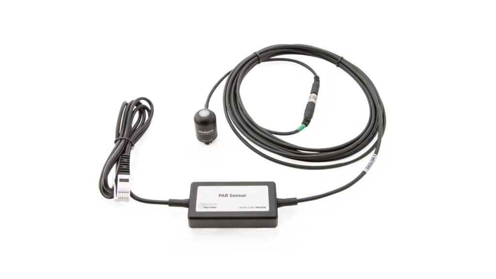
The PAR (Photosynthetically Active Radiation) Sensor measures photosynthetic light levels in both air and water. The sensor responds to visible light in the spectral range that is used by plants in photosynthesis (375–630 nm). It features a waterproof sensor head and connector and reports the Photosynthetic Photon Flux Density (PPFD), which is measured in μmol m-2 s-1 (micromoles of photons per meter squared per second). The sensor is calibrated for use in sunlight, but can also be used to measure PPFD from electric light sources. This sensor is ideal for experiments that investigate photosynthesis and primary productivity and can also be used in many agricultural and environmental science applications.
Note: Vernier products are designed for educational use. Our products are not designed nor are they recommended for any industrial, medical, or commercial process such as life support, patient diagnosis, control of a manufacturing process, or industrial testing of any kind.
What's Included
- PAR Sensor
- Cover for the lens of the PAR sensor
Compatible Software
Choose a platform below to see its compatibility requirements.LabQuest
Interface LabQuest App LabQuest 3 Full support LabQuest 2 Full support LabQuest Full support Computers
Software Interface Graphical Analysis Graphical Analysis (Web App) Logger Pro (discontinued) Logger Lite (discontinued) LabQuest Mini Full support Full support Full support Full support LabQuest 3 Full support Full support Full support Incompatible LabQuest 2 Full support Full support Full support Full support LabQuest Stream Full support 1 Full support 1 Partial support 2 Full support 1 Go! Link Full support Full support Full support Full support LabQuest Full support Full support Full support Full support LabPro Incompatible Incompatible Full support Full support Compatibility Notes
Chromebook
Software Interface Graphical Analysis (Web App) LabQuest Mini Full support LabQuest 3 Full support LabQuest 2 Full support LabQuest Stream Full support 1 Go! Link Full support LabQuest Full support Compatibility Notes
iOS
Software Interface Graphical Analysis Graphical Analysis GW LabQuest Stream Full support Partial support 1 LabQuest 3 Full support 2 Full support 2 LabQuest 2 Full support 2 Full support 2 Compatibility Notes
Android
Software Interface Graphical Analysis Graphical Analysis GW LabQuest Stream Full support Partial support 1 LabQuest 3 Full support 2 Full support 2 LabQuest 2 Full support 2 Full support 2 Compatibility Notes
Arduino
Software Interface Arduino Vernier Arduino® Interface Shield Full support LabVIEW
Software Interface NI LabVIEW SensorDAQ Full support Vernier myDAQ Adapter Full support 1 Go! Link Full support LabQuest Mini Full support LabQuest Stream Full support LabQuest 3 Full support LabQuest 2 Full support LabQuest Full support Compatibility Notes
Texas Instruments
Software Interface EasyData DataMate TI-84 SmartView DataQuest TI-Nspire Software EasyLink Full support 1 Incompatible Full support 2 Full support Full support 2 CBL 2 Full support 3 Full support 3 4 Incompatible Incompatible Incompatible LabPro Full support 3 Full support 3 4 Incompatible Incompatible Incompatible TI-Nspire Lab Cradle Incompatible Incompatible Incompatible Full support Full support Compatibility Notes
Quick Start
- Plug the sensor into the interface (LabQuest 3, LabQuest Mini, etc.).
- Connect the interface to your device.
- If using USB, connect to the USB port on your computer.
- If using Bluetooth® wireless technology, click your interface type and then select your device.
- Prepare for data collection:
- Vernier Graphical Analysis®: Launch the app, if necessary, and click Sensor Data Collection.
- LabQuest® App: Choose New from the File menu.
The software will identify the sensor and load a default data-collection setup. You are now ready to collect data.
Need Additional Information?
Visit the following link:
Using the Product
Sensor Orientation
Sensor orientation is important for getting the best results from the PAR Sensor. When measuring PAR outdoors, the sensor head should be level, with the white lens pointing straight up toward the sky and with the cord pointing toward the north (in the Northern Hemisphere) or toward the south (in the Southern Hemisphere).
When measuring PAR from an artificial light source, the sensor head should be placed with the lens of the sensor facing the center of the light path.
Mounting the PAR Sensor
The PAR Sensor can be permanently mounted to a surface for continuous outdoor use. The sensor head and connector are waterproof and the black electronics box is weatherproof. Care should be taken to keep the electronics box as dry as possible. For best results, the sensor head should be leveled during mounting. The nylon
10–32″ × 3/8″ mounting screw found on the bottom of the sensor head can be used for attaching the PAR Sensor to a solid object.
The sensor should also be mounted such that obstructions do not shade the sensor (e.g., trees, weather station, cell phone tower). Once mounted, the protective cap should be removed from the sensor. The protective cap can still be used as a covering for the sensor when it is not in use
Calibrating the Sensor
The Vernier PAR Sensor is calibrated before shipping and should not need user calibration.
Optional Calibration Check
The Vernier PAR Sensor should not need to be calibrated, but you can verify the calibration using the Clear Sky Calculator (www.clearskycalculator.com). The Clear Sky Calculator for Quantum Sensors reports the theoretical PPFD at any time of day at any location in the world on a cloudless day. The application is most accurate at solar noon in the spring and summer.
Adjusting the Calibration Equation for Other Light Sources
The Vernier PAR Sensor is calibrated for use in sunlight and for broadband artificial light sources. The calibration equation can be adjusted to measure PAR from different light sources, such as LED grow lights and to make the sensor more accurate when used under water. For steps on adjusting the calibration equation please see www.vernier.com/til/3102
Specifications
|
PAR range |
0 to 2500 μmol m-2 s-1 (in full sun) |
|
Absolute accuracy |
±5% (full scale) |
|
Repeatability |
±1% |
|
Long-term drift |
Less than 2% per year |
|
Cosine response
|
45° zenith angle: ± 2% 75° zenith angle: ± 5% |
|
Wavelength range |
370–650 nm |
|
Resolution |
1 μmol m-2 s-1 |
Sensor dimensions | diameter: 2.4 cm height: 3.3 cm cable length: 5 m |
Materials | Anodized aluminum with cast acrylic lens |
Operating environment
| –10 to 60°C 0–100% relative humidity Sensor head and cable can be |
Stored calibration values | slope: 500 μmol m-2 s-1/V intercept: 0 |
Care and Maintenance
Do not wrap the cable tightly around the sensor for storage. Repeatedly doing so can irreparably damage the wires and is not covered under warranty.
Cleaning the PAR Sensor
Debris on the PAR Sensor lens will partially block the optical path and will lead to low readings. Dust and other organic deposits are best removed using water or window cleaner. Never use an abrasive cleaner on the lens. Salt deposits can also accumulate on the sensor lens over time due to evaporation from sea spray, sprinkler irrigation water, or wave splash. Salt deposits should be dissolved with vinegar and then removed using soft cloth or cotton swabs.
PAR Sensor Head Connector
The head of the Vernier PAR Sensor is attached to the main cable using a P68‑rated stainless-steel marine grade (M8) connector. This connector is located 25 cm from the sensor head. The connector is used for removing the sensor head during routine calibration, replacement, or maintenance by the manufacturer. Please do not remove the sensor head from the main cable. For the connector to be waterproof, confirm that the cables are firmly connected and the threaded connectors are finger tight.
PAR Terminology
Radiation that drives photosynthesis is called photosynthetically active radiation (PAR) and is defined as the total amount of radiation across a spectral range of 400 to 700 nm. This means that an ideal PAR sensor would respond equally to all wavelengths of light between 400–700 nm. The summed amount of light across this range is called the photosynthetic photon flux density (PPFD) and is measured in units of micromoles per square meter per second (μmol m-2 s-1). The term PPFD is often shortened to PPF (photosynthetic photon flux) by plant physiologists. The two terms (PPFD and PPF) are interchangeable.
Plant physiologists also refer to sensors that measure PPFD as quantum sensors. A quantum, in this case, refers to the minimum quantity of light (one photon) that is available for absorption by the photosynthetic pigments of plants. In other words, one photon is a single quantum of light that can be used by plants for photosynthesis. Based on this definition, the Vernier PAR Sensor is a quantum sensor.
How the Sensor Works
The Vernier PAR Sensor consists of a waterproof Apogee Instruments SQ series quantum sensor connected to a 5 m cable. The end of the cable is attached to a voltage amplifier located inside a black electronics box. A cable from the electronics box is then connected to the data-collection interface. The sensor head consists of an acrylic lens, filter, photodiode, and signal processing circuitry that is mounted in a waterproof aluminum housing that can be used for continuous PPFD measurements. The sensor head is cosine corrected. This allows the sensor to maintain accuracy when light hits the sensor head at different angles. Light hitting the lens of the sensor head produces an analog voltage that is amplified by the electronics box. This amplified voltage is then converted to PPFD by the data‑collection software.
Troubleshooting
For troubleshooting and FAQs, see www.vernier.com/til/3113
Warranty
Warranty information for this product can be found on the Support tab at www.vernier.com/par-bta/#support
General warranty information can be found at www.vernier.com/warranty
Contact Support
Fill out our online support form or call us toll-free at 1-888-837-6437.