Soil Moisture Sensor User Manual
Order Code: SMS-BTA
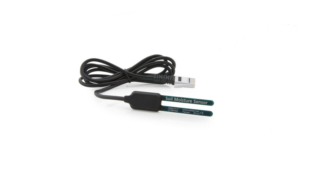
The Soil Moisture Sensor is used to measure the volumetric water content of soil. This makes it ideal for performing experiments in courses such as soil science, agricultural science, environmental science, horticulture, botany, and biology. Use the Soil Moisture Sensor to:
- Measure the loss of moisture over time due to evaporation and plant uptake.
- Evaluate optimum soil moisture contents for various species of plants.
- Monitor soil moisture content to control irrigation in greenhouses.
- Enhance your Bottle Biology™ experiments.
Note: Vernier products are designed for educational use. Our products are not designed nor are they recommended for any industrial, medical, or commercial process such as life support, patient diagnosis, control of a manufacturing process, or industrial testing of any kind.
Compatible Software
Choose a platform below to see its compatibility requirements.LabQuest
Interface LabQuest App LabQuest 3 Full support LabQuest 2 Full support LabQuest Full support Computers
Software Interface Graphical Analysis Graphical Analysis (Web App) Logger Pro (discontinued) Logger Lite (discontinued) LabQuest Mini Full support Full support Full support Full support LabQuest 3 Full support Full support Full support Incompatible LabQuest 2 Full support Full support Full support Full support LabQuest Stream Full support 1 Full support 1 Partial support 2 Full support 1 Go!Link Full support Full support Full support Full support LabQuest Full support Full support Full support Full support LabPro Incompatible Incompatible Full support Full support Compatibility Notes
Chromebook
Software Interface Graphical Analysis (Web App) LabQuest Mini Full support LabQuest 3 Full support LabQuest 2 Full support LabQuest Stream Full support 1 Go!Link Full support LabQuest Full support Compatibility Notes
iOS
Software Interface Graphical Analysis Graphical Analysis GW LabQuest Stream Full support Full support LabQuest 3 Full support 1 Full support 1 LabQuest 2 Full support 1 Full support 1 Compatibility Notes
Android
Software Interface Graphical Analysis Graphical Analysis GW LabQuest Stream Full support Full support LabQuest 3 Full support 1 Full support 1 LabQuest 2 Full support 1 Full support 1 Compatibility Notes
Arduino
Software Interface Arduino Vernier Arduino® Interface Shield Full support LabVIEW
Software Interface NI LabVIEW SensorDAQ Full support Vernier myDAQ Adapter Full support 1 Go!Link Full support LabQuest Mini Full support LabQuest Stream Full support LabQuest 3 Full support LabQuest 2 Full support LabQuest Full support Compatibility Notes
Texas Instruments
Software Interface EasyData DataMate TI-84 SmartView DataQuest TI-Nspire Software EasyLink Full support 1 Incompatible Full support 2 Full support Full support 2 CBL 2 Full support 3 Full support 3 4 Incompatible Incompatible Incompatible LabPro Full support 3 Full support 3 4 Incompatible Incompatible Incompatible TI-Nspire Lab Cradle Incompatible Incompatible Incompatible Full support Full support Compatibility Notes
Quick Start
- Plug the sensor into the interface (LabQuest 3, LabQuest Mini, etc.).
- Connect the interface to your device.
- If using USB, connect to the USB port on your computer.
- If using Bluetooth® wireless technology, click your interface type and then select your device.
- Prepare for data collection:
- Vernier Graphical Analysis®: Launch the app, if necessary, and click Sensor Data Collection.
- LabQuest® App: Choose New from the File menu.
The software will identify the sensor and load a default data-collection setup. You are now ready to collect data.
Need Additional Information?
Visit the following link:
Using the Product
Positioning the sensor
Figure 1 shows the proper placement of the Soil Moisture Sensor. The prongs should be oriented horizontally, but rotated onto their side, like a knife poised to cut food, so that water does not pool on the flat surface of the prongs.
The horizontal orientation of the sensor ensures the measurement is made at a particular soil depth. The entire sensor can be placed vertically, but because soil moisture often varies by depth, this is not usually the desired orientation. To position the sensor, use a thin implement such as a trenching shovel to make the pilot hole in the soil. Place the sensor into the hole, making sure the entire length of the sensor is covered. Press down on the soil along either side of the sensor with your fingers. Continue to compact the soil around the sensor by pressing down on the soil with your fingers until you have made at least five passes along the sensor. This step is important, as the soil adjacent to the sensor surface has the strongest influence on the sensor readings.
Removing the Sensor
When removing the sensor from the soil, do not pull it out of the soil by the cable. Doing so may break internal connections and make the sensor unusable.
What is Volumetric Water Content?
In very simplified terms, dry soil is made up of solid material and air pockets, called pore spaces. A typical volumetric ratio would be 55% solid material and 45% pore space. As water is added to the soil, the pore spaces begin to fill with water. Soil that seems damp to the touch might now have 55% minerals, 35% pore space and 10% water. This would be an example of 10% volumetric water content. The maximum water content in this scenario is 45% because at that value, all the available pore space has been filled with water. This soil is referred to as being saturated, because at 45% volumetric water content, the soil can hold no more water.
Videos
Calibrating the Sensor
Optional Calibration Procedure
It is not usually necessary to perform a new calibration when using the Soil Moisture Sensor. The Soil Moisture Sensor has a stored calibration that will give good results. If, however, very accurate readings are needed, a calibration using the sample soil type to be measured is recommended. Two methods are described below. Method 1 is faster and easier, but potentially less accurate than Method 2.
Calibration Method 1: Two-Point Calibration
This is the faster and easier of the two methods, but is potentially less accurate.
- Dry the soil in a drying oven at 105˚C for 24 hours.
- Obtain a water-tight container that is large enough to fully insert the sensor with room for at least 2 cm on all sides. A plastic shoe box or similar works well.
- When cool, break up any large clods until all soil fits through a 5 mm screen.
- Connect the Soil Moisture Sensor to the interface and start the data-collection program.
-
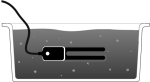
Pour the soil into the container and position the sensor as shown. The prongs should be oriented horizontally, but rotated onto their side–like a knife poised to cut food–so that water does not pool on the flat surface of the prongs.
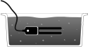 Figure 2
 - Press down on the soil along either side of the sensor with your fingers. Continue to compact the soil around the sensor by pressing down on the soil with your fingers until you have made five passes along the sensor.
- Add more soil on top of the compacted soil so that the sensor is buried at least 3 cm below the soil surface.
- Compact the soil again using a clenched fist.
- Enter the calibration routine of your program. Keep this first calibration point and assign a value of 0. This represents 0% volumetric water content.
- Remove the sensor from the soil.
- Determine the approximate volume of soil used. This can be done by packing it into a large, graduated beaker.
- Return the soil to the calibration container.
- Obtain a volume of distilled water that equals 45% of the volume of the soil. If, for example, you used 3500 mL of soil, you would obtain 1575 mL of distilled water.
- Add the distilled water to the soil and mix well.
- Position the sensor in the wet soil, again making sure the sensor is completely covered and that there are no gaps between the soil and the sensor.
- Keep this second calibration point, assigning it a value of 45. This represents 45% volumetric water content.
- Your sensor is now calibrated for this soil type. Note: You may want to record the calibration values for future use.
Calibration Method 2: Multiple-Point Calibration
This method is more accurate, but requires more time and effort than Method 1.
- Obtain and number 12 drying jars. The jars must be able to withstand the 105°C temperature of the drying oven.
- Weigh and record the mass of each jar.
- Prepare the dry soil by breaking up large clods until all soil fits through a
5 mm screen. Note: The soil should be fairly dry, but does not need to be oven-dry for this method. - Obtain a water-tight container that is large enough to fully insert the sensor with room for at least 2 cm on all sides. A plastic shoe box or similar works well.
- Connect the Soil Moisture Sensor to the interface and start the data-collection program.
-
Pour the soil into the container position the sensor as shown. The prongs should be oriented horizontally, but rotated onto their side–like a knife poised to cut food– so that water does not pool on the flat surface of the prongs.
Figure 3 - Press down on the soil along either side of the sensor with your fingers. Continue to compact the soil around the sensor by pressing down on the soil with your fingers until you have made five passes along the sensor.
- Add more soil on top of the compacted soil so that the sensor is buried at least 3 cm below the soil surface.
- Compact the soil again using a clenched fist.
- Enter the calibration portion of the data-collection program and record the voltage reading from the sensor. Note: In this method, entering the calibration portion of the program is used only to obtain a raw voltage reading from the sensor. You will not be completing a typical 2-point calibration in the software.
- Use a soil core tool to take three volumetric soil samples adjacent to the sensor.
- Insert the sampling cylinder fully into the soil.
- Remove the soil core.
- Dispense the core into a drying jar.
- Weigh and record the mass of the jar plus soil.
- Repeat Steps a–d for two additional core samples.
- Remove the sensor from the soil.
- Decide on a standard volume of distilled water that will increase the water content by 3 to 10% for each measurement. If you are unsure about the amount of water to add, measure the volume of soil you are using. Use a volume of distilled water equal to 5% of the volume of the soil.
- Add one aliquot of distilled water to the soil in the amount decided upon in Step 13. To avoid clumping, add the water in small amounts, mixing thoroughly.
- Replace the sensor in the soil. Press down on the soil along either side of the sensor with your fingers. Continue to compact the soil around the sensor by pressing down on the soil with your fingers until you have made five passes along the sensor.
- Add more soil on top of the compacted soil so that the sensor is buried at least
- Compact the soil again using a clenched fist.
- Record the voltage reading from the sensor.
- Repeat Steps 11–18 two more times for a total of four levels of water content.
- Dry and weigh the 12 soil samples to determine gravimetric water content.
- Place the jars in a drying oven for 24 hours at 105˚C.
- Allow the samples to cool until the soil temperature is near ambient.
- After cooling, weigh the soil samples again to determine dry weight.
- Determine the volumetric water content, θ, for each of the four samples.
Calculate the gravimetric water content, w.

where m is the mass and the subscripts w and m refer to water and minerals.
Calculate the bulk density, ρb.

where Vt is the total volume of the sample.
Calculate the volumetric water content.

The density of water, ρw, is 1 g/cm3.
Example
| Soil sampling volume (Vt) | 16.1 cm3 |
| Soil sample initial weight (with jar) | 84.065 g |
| Dried sample weight (with jar) | 81.113 g |
| Jar weight (tare) | 57.894 g |
| Mass of water (initial–dry weight) (mw) | 2.952 g |
| Mass of dry soil (dry–tare weight) (mm) | 23.219 g |
 |  |

- Construct a calibration curve by graphing volumetric water content vs. the corresponding sensor output voltage at that water content.
- Perform a linear regression on the calibration curve and record the slope and intercept.
- Connect the sensor and start your data-collection program.
- Proceed to the calibration portion of the program and manually enter the values for slope and intercept.
- Your sensor is now calibrated for this soil type. Note: You may want to record the calibration values for future use.
Specifications
|
Range: |
0 to 45% volumetric water content in soil (capable of 0 to 100% VWC with alternate calibration) |
||
|
Accuracy |
±4% typical |
||
|
Resolution |
0.1% |
||
|
Power |
3 mA @ 5VDC |
||
|
Operating temperature |
–40°C to +60°C |
||
|
Dimensions |
Dimensions: 8.9 cm × 1.8 cm × 0.7 cm |
||
|
Stored calibration |
|
Care and Maintenance
Do not wrap the cable tightly around the sensor for storage. Repeatedly doing so can irreparably damage the wires and is not covered under warranty.
How the Sensor Works
The Soil Moisture Sensor uses capacitance to measure dielectric permittivity of the surrounding medium. In soil, dielectric permittivity is a function of the water content. The sensor creates a voltage proportional to the dielectric permittivity, and therefore the water content of the soil.
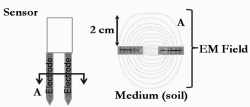
The sensor averages the water content over the entire length of the sensor. There is a 2 cm zone of influence with respect to the flat surface of the sensor, but it has little or no sensitivity at the extreme edges. Figure 4 shows the electromagnetic field lines along a cross-section of the sensor, illustrating the 2 cm zone of influence.
Troubleshooting
For troubleshooting and FAQs, see www.vernier.com/til/1617
Repair Information
If you have watched the related product video(s), followed the troubleshooting steps, and are still having trouble with your Soil Moisture Sensor, contact Vernier Technical Support at support@vernier.com or call 888-837-6437. Support specialists will work with you to determine if the unit needs to be sent in for repair. At that time, a Return Merchandise Authorization (RMA) number will be issued and instructions will be communicated on how to return the unit for repair.
Warranty
Warranty information for this product can be found on the Support tab at www.vernier.com/sms-bta/#support
General warranty information can be found at www.vernier.com/warranty
Disposal
When disposing of this electronic product, do not treat it as household waste. Its disposal is subject to regulations that vary by country and region. This item should be given to an applicable collection point for the recycling of electrical and electronic equipment. By ensuring that this product is disposed of correctly, you help prevent potential negative consequences on human health or on the environment. The recycling of materials will help to conserve natural resources. For more detailed information about recycling this product, contact your local city office or your disposal service.
Battery recycling information is available at www.call2recycle.org
Do not puncture or expose the battery to excessive heat or flame.
 The symbol, shown here, indicates that this product must not be disposed of in a standard waste container.
Contact Support
Fill out our online support form or call us toll-free at 1-888-837-6437.