Vernier Energy Sensor User Manual
Order Code: VES-BTA
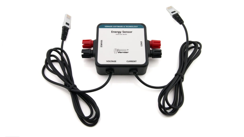
The Vernier Energy Sensor allows students to easily measure current and voltage. Source terminals connect to energy output sources such as model wind turbines or solar panels, and Load terminals connect to loads such as LEDs, water pumps, resistors, or variable loads.
Note: Vernier products are designed for educational use. Our products are not designed nor are they recommended for any industrial, medical, or commercial process such as life support, patient diagnosis, control of a manufacturing process, or industrial testing of any kind.
Compatible Software
Choose a platform below to see its compatibility requirements.LabQuest
Interface LabQuest App LabQuest 3 Full support LabQuest 2 Full support LabQuest Full support Computers
Software Interface Graphical Analysis Graphical Analysis (Web App) Logger Pro (discontinued) Logger Lite (discontinued) LabQuest Mini Full support Full support Full support Full support LabQuest 3 Full support Full support Full support Incompatible LabQuest 2 Full support Full support Full support Full support LabQuest Stream Full support 1 Full support 1 Partial support 2 Full support 1 Go! Link Partial support 3 Partial support 3 Partial support 3 Partial support 3 LabQuest Full support Full support Full support Full support LabPro Incompatible Incompatible Full support Full support Compatibility Notes
Chromebook
Software Interface Graphical Analysis (Web App) LabQuest Mini Full support LabQuest 3 Full support LabQuest 2 Full support LabQuest Stream Full support 1 Go! Link Partial support 2 LabQuest Full support Compatibility Notes
iOS
Software Interface Graphical Analysis Graphical Analysis GW LabQuest Stream Full support Partial support 1 LabQuest 3 Full support 2 Full support 2 LabQuest 2 Full support 2 Full support 2 Compatibility Notes
Android
Software Interface Graphical Analysis Graphical Analysis GW LabQuest Stream Full support Partial support 1 LabQuest 3 Full support 2 Full support 2 LabQuest 2 Full support 2 Full support 2 Compatibility Notes
Arduino
Software Interface Arduino Vernier Arduino® Interface Shield Full support LabVIEW
Software Interface NI LabVIEW SensorDAQ Full support Vernier myDAQ Adapter Full support 1 Go! Link Partial support 2 LabQuest Mini Full support LabQuest Stream Full support LabQuest 3 Full support LabQuest 2 Full support LabQuest Full support Compatibility Notes
Texas Instruments
Software Interface EasyData DataMate TI-84 SmartView DataQuest TI-Nspire Software EasyLink Partial support 1 2 Incompatible Partial support 1 3 Partial support 1 Partial support 1 3 CBL 2 Partial support 4 5 Partial support 4 5 6 Incompatible Incompatible Incompatible LabPro Partial support 4 5 Partial support 4 5 6 Incompatible Incompatible Incompatible TI-Nspire Lab Cradle Incompatible Incompatible Incompatible Full support 7 Full support 7 Compatibility Notes
Quick Start
- Plug the sensor into the interface (LabQuest 3, LabQuest Mini, etc.).
- Connect the interface to your device.
- If using USB, connect to the USB port on your computer.
- If using Bluetooth® wireless technology, click your interface type and then select your device.
- Prepare for data collection:
- Vernier Graphical Analysis®: Launch the app, if necessary, and click Sensor Data Collection.
- LabQuest® App: Choose New from the File menu.
The software will identify the sensor and load a default data-collection setup. You are now ready to collect data.
 WARNING: To avoid possible electric shock or personal injury, do not connect the red or black leads to household power. This product is designed to measure low-voltage sources such as classroom-scale wind turbines and small solar panels. It should never be connected to an electrical outlet.
Need Additional Information?
Visit the following link:
Using the Product
Zeroing the Sensor
Both Current and Voltage should be zeroed in the data-collection software prior to collecting data. To do this, disconnect the load and source and connect the two Load terminals with a wire. Zero the sensors in the software. Note: Any resistance value shown in the meter in the software is not meaningful when the current and voltage values are near zero.
Connecting Devices to the Energy Sensor
The Vernier Energy Sensor provides a pair of five-way binding posts, labeled Source, to connect the device that is generating power, such as a model wind turbine, solar panel, battery, power supply, or function generator. Another pair of binding post terminals, labeled Load, connect to the load. The load can be any electrical device that is meant to run on DC electricity at a voltage that matches the power source. Examples include the Vernier Variable Load (order code VES‑VL), the Vernier Resistor Board (order code VES‑RB), single component resistors, motors, or LEDs.
These terminals will accept standard banana plugs, alligator clips, or bare wires and provide a solid electrical connection.
Videos
Specifications
|
Source input potential range |
± 30 V |
|
Source input current range |
± 1000 mA |
|
Linearity
|
|
|
Resolution |
|
|
Input impedance |
Potential Sensor: > 2 MΩ |
|
Insertion resistance |
Current Sensor: 0.1 Ω |
|
Frequency response
|
|
|
Stored calibration (Potential Sensor) |
|
|
Stored calibration (Current Sensor) |
|
How the Sensor Works
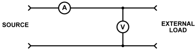
The Vernier Energy Sensor has two BTA connectors: a Voltage connector and a Current connector. If you connect only the Voltage connector or the Current connector, the Energy Sensor will function as a simple voltage or current sensor. When both connectors are connected to a Vernier interface, Graphical Analysis and LabQuest app automatically identifies the sensor as the Energy Sensor and loads the appropriate a data- collection setup for this sensor. Calculated columns and meters for power, resistance, and energy are created in the file.
If you are using other software listed in the Compatible Software section, you may have to manually set up the calculated columns and meters for power, resistance, and energy.
If you are using other software listed in the Compatible Software section, you may have to manually set up the calculated columns and meters for power, resistance, and energy.
The Vernier Energy Sensor measures the potential across the load, as well as the current through the load.
Care and Maintenance
Do not wrap the cable tightly around the sensor for storage. Repeatedly doing so can irreparably damage the wires and is not covered under warranty.
Troubleshooting
For troubleshooting and FAQs, see www.vernier.com/til/3181
Repair Information
If you have watched the related product video(s), followed the troubleshooting steps, and are still having trouble with your Vernier Energy Sensor, contact Vernier Technical Support at support@vernier.com or call 888-837-6437. Support specialists will work with you to determine if the unit needs to be sent in for repair. At that time, a Return Merchandise Authorization (RMA) number will be issued and instructions will be communicated on how to return the unit for repair.
Accessories/Replacements
| Item | Order Code |
|---|---|
|
VES-VL |
|
| Vernier Resistor Board |
VES-RB |
| KidWind Advanced Wind Experiment Kit |
KW-AWX |
| KidWind Basic Wind Experiment Kit |
KW-BWX |
| KidWind MINI Wind Turbine |
KW-MWT |
| KidWind 2V/400mA Solar Panel |
KW-SP2V |
Warranty
Warranty information for this product can be found on the Support tab at www.vernier.com/ves-bta/#support
General warranty information can be found at www.vernier.com/warranty
Contact Support
Fill out our online support form or call us toll-free at 1-888-837-6437.