Instrumentation Amplifier User Manual
Order Code: INA-BTA
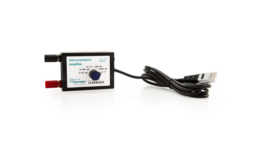
Our Instrumentation Amplifier is designed to condition signals to be compatible with Vernier interface products. The amplifier provides the necessary gain and offset to allow you to connect a wide variety of measurement equipment to your interface and electronically collect, store, and analyze the data. The Instrumentation Amplifier can also be used as a voltage probe in circuits having small potential differences, such as when investigating resistivity in metal rods (see Experiment #9, Electrical Resistance, in Advanced Physics with Vernier—Beyond Mechanics).
Although you may calibrate your software to display otherwise, your interface unit can only measure a potential difference (voltage). Many laboratory instruments produce a voltage that varies as the instrument reading changes. Examples include gas chromatographs, spectrophotometers, light meters, and sound meters. If you are familiar with electronics, you may be able to go inside the instrument and find out where to measure this voltage signal. Some instruments have chart recorder terminals that are designed for this purpose. Test the voltage range of this signal. If the voltage happens to vary over a range that matches your interface, then the signal can be fed directly to the interface and monitored by the software. More likely, the voltage signal will need to be amplified before it can be monitored.
Note: Vernier products are designed for educational use. Our products are not designed nor are they recommended for any industrial, medical, or commercial process such as life support, patient diagnosis, control of a manufacturing process, or industrial testing of any kind.
Compatible Software
Choose a platform below to see its compatibility requirements.LabQuest
Interface LabQuest App LabQuest 3 Full support LabQuest 2 Full support LabQuest Full support Computers
Software Interface Graphical Analysis Graphical Analysis (Web App) Logger Pro (discontinued) Logger Lite (discontinued) LabQuest Mini Full support Full support Full support Full support LabQuest 3 Full support Full support Full support Incompatible LabQuest 2 Full support Full support Full support Full support LabQuest Stream Full support 1 Full support 1 Partial support 2 Full support 1 Go! Link Full support Full support Full support Full support LabQuest Full support Full support Full support Full support LabPro Incompatible Incompatible Full support Full support Compatibility Notes
Chromebook
Software Interface Graphical Analysis (Web App) LabQuest Mini Full support LabQuest 3 Full support LabQuest 2 Full support LabQuest Stream Full support 1 Go! Link Full support LabQuest Full support Compatibility Notes
iOS
Software Interface Graphical Analysis Graphical Analysis GW LabQuest Stream Full support Full support LabQuest 3 Full support 1 Full support 1 LabQuest 2 Full support 1 Full support 1 Compatibility Notes
Android
Software Interface Graphical Analysis Graphical Analysis GW LabQuest Stream Full support Full support LabQuest 3 Full support 1 Full support 1 LabQuest 2 Full support 1 Full support 1 Compatibility Notes
Arduino
Software Interface Arduino Vernier Arduino® Interface Shield Full support LabVIEW
Software Interface NI LabVIEW SensorDAQ Full support Vernier myDAQ Adapter Full support 1 Go! Link Full support LabQuest Mini Full support LabQuest Stream Full support LabQuest 3 Full support LabQuest 2 Full support LabQuest Full support Compatibility Notes
Texas Instruments
Software Interface EasyData DataMate TI-84 SmartView DataQuest TI-Nspire Software EasyLink Full support 1 Incompatible Full support 2 Full support Full support 2 CBL 2 Full support 3 Full support 3 4 Incompatible Incompatible Incompatible LabPro Full support 3 Full support 3 4 Incompatible Incompatible Incompatible TI-Nspire Lab Cradle Incompatible Incompatible Incompatible Full support Full support Compatibility Notes
Quick Start
- Plug the sensor into the interface (LabQuest 3, LabQuest Mini, etc.).
- Connect the interface to your device.
- If using USB, connect to the USB port on your computer.
- If using Bluetooth® wireless technology, click your interface type and then select your device.
- Prepare for data collection:
- Vernier Graphical Analysis®: Launch the app, if necessary, and click Sensor Data Collection.
- LabQuest® App: Choose New from the File menu.
The software will identify the sensor and load a default data-collection setup. You are now ready to collect data.
Need Additional Information?
Visit the following link:
Using the Product
Using the Instrumentation Amplifier with a Gas Chromatograph
If your voltage readings are noisy, you should connect the Earth ground of the Gas Chromatograph to the black post on the end of the Instrumentation Amplifier box where the sensor cable is located. Connecting the Earth ground in this way should reduce or eliminate any electronic noise.
Also, keep in mind that LabQuest App has a Peak Integration tool that can be used to integrate and quantify GC peaks. Once you have collected GC data, you can simply choose Peak Integration from the Analyze menu. On this dialog, you can select and integrate peaks one at a time. Note: This feature is not available in Graphical Analysis or Graphical Analysis Pro.
Using the Instrumentation Amplifier as a Current Meter
The Instrumentation Amplifier can be used to monitor current instead of voltage. By placing a resistor between the terminals, the voltage amplified becomes proportional to the current according to
I = (V/G)/R
where V is the voltage read, G is the gain setting of the amplifier, and R is the resistor value. To monitor current in a circuit, you want to choose a small resistor value; for example 0.1Ω or 1Ω resistor with a rating of at least 1W.
For monitoring a current output device, you will need to choose a termination resistor that is appropriate for that device (call for details or consult the manufacturers specifications). For best accuracy, perform a calibration using an open circuit and a known current source. One of the Vernier Current Probes can be used for this application.
Specifications
|
Gain settings |
150, 75, 7.5, 15, 3, and 1.5±5% |
|||
|
Linearity |
1% |
|||
|
Power |
2.5 mA @ 5VDC |
|||
|
Frequency response |
0-10kHz (f3dB) |
|||
|
Impedance |
1MΩ to ground |
|||
|
Calibration values
|
||||
Care and Maintenance
Do not wrap the cable tightly around the sensor for storage. Repeatedly doing so can irreparably damage the wires and is not covered under warranty.
How the Sensor Works
The amplifier is a monolithic instrumentation amplifier with variable gain and offset settings. An instrumentation amplifier contains precision feedback components and circuitry that is necessary for small signal amplification.
The Instrumentation Amplifier does three primary tasks:
- Provides six different gain settings to amplify small signals to levels appropriate for our interfacing equipment.
- Offsets the voltage so it is always in the range of 0 to 3.5 volts. This allows the amplifier to be used with negative signals even though some of our interfaces only use 0-5 V inputs.
- Provides filtering of high frequency signals. Wires that connect the instrument to the amplifier are prone to pick up electrical noise much like a radio antenna. By filtering out these signals, only the data of interest are left.
When set to the 20 mV, 200 mV, and 1 V positions, the amplification is set to 150, 15, and 3 respectively. The difference in voltage at the red and black terminal is amplified and output with reference to ground.
When set to ±20 mV, ±200 mV, and ±1 V setting, the amplification is set to 75, 7.5, and 1.5 respectively. The difference in voltage at the red and black terminal is amplified and output with reference to 1.85 V.
Tips
Amplify an Instrument's Chart Recorder Output
Many lab instruments provide a low voltage output designed for interfacing to a chart recorder. You may use these outputs with the Instrumentation Amplifier to interface to a computer. This graph shows the output of a gas chromatograph processing a sample of fatty acids dissolved in toluene solvent.
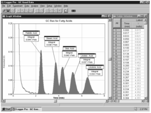
GOW-Mac Series 350 Gas Chromatograph
Troubleshooting
For troubleshooting and FAQs, see www.vernier.com/til/1418
Repair Information
If you have followed the troubleshooting steps and are still having trouble with your Instrumentation Amplifier, contact Vernier Technical Support at support@vernier.com or call 888-837-6437. Support specialists will work with you to determine if the unit needs to be sent in for repair. At that time, a Return Merchandise Authorization (RMA) number will be issued and instructions will be communicated on how to return the unit for repair.
Accessories/Replacements
| Item | Order Code |
|---|---|
|
RRS |
|
|
VCB-GATOR |
Warranty
Warranty information for this product can be found on the Support tab at www.vernier.com/ina-bta/#support
General warranty information can be found at www.vernier.com/warranty
Contact Support
Fill out our online support form or call us toll-free at 1-888-837-6437.