The SensorDAQ interface is perfect for teaching NI LabVIEW or for building sensor-control student projects using NI LabVIEW software.
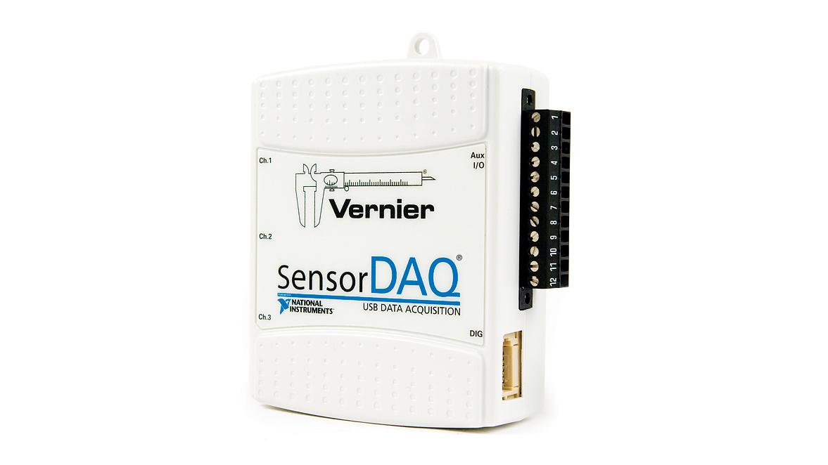
Included are four channels for a quick and easy way to add Vernier sensors without external wiring or signal conditioning. There is a screw terminal for digital I/O, analog output, counter, +5 Volt line, and 2 more analog inputs to build circuits, create custom sensors, control RC servo motors, turn on electronic devices, and more.
- Connect over 55 Vernier analog and digital sensors
- Use with NI LabVIEW software version 2009 or newer (not included)
- Screw terminal connector provides 12 auxiliary channels